A Dual Channel RF Generator
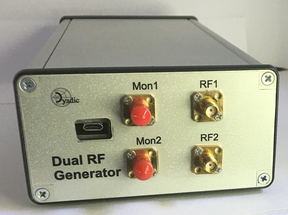
Simple RF Generator - Front
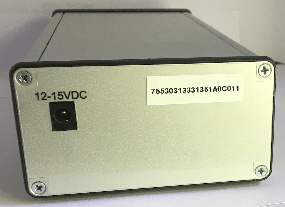
Simple RF Generator - Back
Hardware Setup
Note that when using the rfgen hardware it's necessary to use the power up as documented in the HMC833 Applications Information. In summary, this sequence is:
Ensure that the USB connection is made from the microcontroller to the client host before powering on the rfgen hardware.
Power up the rfgen hardware.
Application Usage
The rfgen app is started from the command line. If the app is started
without specifying a serial device (using the -d option) a list of
suitable connected devices will be presented in the Control Port drop
down in app UI.
or
The app may also be started from the app launcher if this is configured and running.
Once running the app is used as follows:
Select the RF generator hardware control port. This is only necessary when the USB control port device has not been specified either on the command line of via the app launcher.
Initialize the RF generator hardware by selecting the
InitializeUI button.The RF generator channels can now be configured using the relevant channel controls.
Figure 1: RF signal generator app
Channel controls
Figure 2: RF signal generator channel controls
Command line usage:
usage: rfgen.py [-h] [--nogui] [--no_cal_data] [-d DEVICE] [-b BAUDRATE] [-A IPADDR] [-P PORT]

A simple RF signal generator.

optional arguments:
  -h, --help            show this help message and exit
  --nogui               Disable GUI and run 'headless'
  --no_cal_data         No output power calibration data should be used
  -d DEVICE, --device DEVICE
                        The serial device for testing
  -b BAUDRATE, --baudrate BAUDRATE
                        Baud rate (default: 0)
  -A IPADDR, --ipaddr IPADDR
                        IP address for to bind the RPyC server instance
  -P PORT, --port PORT  TCP port for the RPyC server instance
Software control
Software control of the signal generator is done via the rfgen
RPyC service provided by the SimpleRfGen reference design app.
If the app is run 'headless' (by specifying the '--nogui' command line
option) then the serial device must also be specified via the command
line. By default the rfgen service will listen on port 18864 of the
localhost interface. This may be changed by using the -P and -A
command line options when starting the app.
>>> import rpyc
>>> rfgen = rpyc.connect('127.0.0.1', 18864)
>>> rfgen.root.initialize()

>>> chan1 = rfgen.root.channels['Chan 1']
>>> chan1.level = -10.0
>>> chan1.plo_ctl.freq = 1500
>>> chan1.configure()
If there are detector heads connected to the ports on the rear of the
signal generator they can be initialized for use. The
initialize_detector method will return True if a power detector head is
connected and successfully initialized for use. False is returned if
there is no power head connected on the associated port.
>>> rfgen.root.initialize_detector('Chan 1')
True
>>> rfgen.root.initialize_detector('Chan 2')
False
When a power detector head is available for use the signal power on the detector input is read as follows:
>>> det_ctl1 = rfgen.root.detector('Chan 1')
>>> det_ctl1.avg = 4
>>> rfgen.root.measure_power('Chan 1')
-36.35756473058082
Here a reference to the associated PwrDetectorController is used to set the
number of individual power measurements to average before returning the
result. Note that the signal frequency at which the measurement is made
will, by default, be set to the output frequency of the signal generator
channel associated with the detector head. If the detector is connected to
some other signal source then the frequency can be specified using the
freq parameter. For example:
If the power detector head is connected to the signal source to be measured
by some intermediate element (such as an attenuator or amplifier) then it's
necessary to use calibration data in order to adjust the measured values
as reported by the measure_power method. See the Calibration and
correction section of Dual Channel RF Power Meter reference design for a
description of the format of the calibration data.
The calibration data can be loaded directly from a file using the PwrDetectorController load_caldata method:
>>> cal_file = './PowerMeter/app/cal-files/12dB-atten-5640-128-100-6000MHz.json'
>>> det_ctl1.load_caldata(cal_file)
>>> det_ctl1.apply_correction = True
>>> rfgen.root.measure_power('Chan 1')
-24.51756473058082
Note that by default, calibration corrections are turned off and should be
turned on explicitly as shown above. Note also that the file path to load
the calibration data file will be relative to the directory where the rfgen
app was started (in this case referencedesigns/SimpleRFGen/app)
If the power detector head is connected to the monitor output of the signal generator channel, the actual channel output power can be calculated from the coupling and insertion_loss methods of the default bridge coupler instance as shown here:
>>> from rfblocks import BridgeCoupler
>>> coupler = BridgeCoupler()
>>> mon_pwr = rfgen.root.measure_power('Chan 1')
>>> mon_pwr - coupler.coupling(1500) + coupler.insertion_loss(1500)
-10.299810041112663
RFGen service API
def initialize(self) -> None:
    """Initialize the service app and associated hardware modules.

    >>> rfgen = rpyc.connect('127.0.0.1', 18864)
    >>> rfgen.root.initialize()
    """

def initialize_detector(self, chan_id: str) -> bool:
    """Initialize the power detector connected to the specified channel.

    :param chan_id: A signal generator channel id.
        This will be one of "Chan 1" or "Chan 2".
    :type chan_id: str

    :return: True if there is a detector connected, False if no
        detector connected.
    """

@property
def channels(self) -> Dict[str, PLOChan]:
    """Return a dictionary of the signal generator channel objects.

    :return: A dictionary of ``PLOChan`` instances keyed using the
    signal generator channel id  ("Chan 1" and "Chan 2").

    >>> rfgen = rpyc.connect('127.0.0.1', 18864)
    >>> rfgen.root.initialize()
    >>> chans = rfgen.root.channels

    >>> chan_id = 'Chan 1'
    >>> chans[chan_id].plo_ctl.freq = 1500.0
    >>> rfgen.root.configure_plo_freq(chan_id)

    """

def configure_plo_freq(self, chan_id: str) -> None:
    """Update the PLO module output frequency for the specified channel.

    :param chan_id: A signal generator channel id.
        This will be one of "Chan 1" or "Chan 2".
    :type chan_id: str

    >>> rfgen = rpyc.connect('127.0.0.1', 18864)
    >>> rfgen.root.initialize()
    >>> chans = rfgen.root.channels

    >>> chan_id = 'Chan 1'
    >>> chans[chan_id].plo_ctl.freq = 1500.0
    >>> rfgen.root.configure_plo_freq(chan_id)

    """

def configure_plo(self, chan_id: str) -> None:
    """Update the PLO module hardware for the specified channel.

    Note that this should only be used when the generator is
    in calibration mode.

    .. seealso:: :meth:`.RFGenService.set_calibration_mode` and

    :param chan_id: A signal generator channel id.
        This will be one of "Chan 1" or "Chan 2".
    :type chan_id: str

    >>> rfgen = rpyc.connect('127.0.0.1', 18864)
    >>> rfgen.root.initialize()
    >>> chans = rfgen.root.channels

    >>> chan_id = 'Chan 1'
    >>> chans[chan_id].plo_ctl.buffer_gain = \
    ...     hmc833.OutputBufferGain.MAXGAIN_MINUS_6DB
    >>> rfgen.root.configure_plo(chan_id)

    """

def configure_atten(self, chan_id: str) -> None:
    """Update step attenuator module hardware for the specified channel.

    Note that this should only be used when the generator is
    in calibration mode.

    .. seealso:: :meth:`.RFGenService.set_calibration_mode` and

    :param chan_id: A signal generator channel id.
        This will be one of "Chan 1" or "Chan 2".
    :type chan_id: str

    >>> rfgen = rpyc.connect('127.0.0.1', 18864)
    >>> rfgen.root.initialize()
    >>> chans = rfgen.root.channels

    >>> chan_id = 'Chan 2'
    >>> chans[chan_id].atten_ctl.attenuation = 10.0
    >>> rfgen.root.configure_atten(chan_id)

    """

def detector(self, chan_id: str) -> Optional[PwrDetectorController]:
    """Return the controller associated with the power detector
    connected to the specified channel.

    :param chan_id: A signal generator channel id.
        This will be one of "Chan 1" or "Chan 2".
    :type chan_id: str

    :return: An instance of PwrDetectorController if there is a
        detector connected, None if no detector connected.
    """

def measure_power(self, chan_id: str) -> float:
    """Measure the signal power currently at the input of the power detector
    currently attached to the specified channel.

    :param chan_id: A signal generator channel id.
        This will be one of "Chan 1" or "Chan 2".
    :type chan_id: str

    :return: The measured signal power in dBm.

    :raises: KeyError
        If there is no detector currently connected to the specified
        channel.
    """

def set_channel_output(self, chan_id, freq, lvl, ignore_cal_state=False):
    """Set output frequency and power of the specified channel.

    :param chan_id: A signal generator channel id.
        This will be one of "Chan 1" or "Chan 2".
    :type chan_id: str
    :param freq: The output signal frequency (in MHz)
    :type freq: float
    :param lvl: The output signal power (in dBm)
    :type lvl: float
    :param ignore_cal_state: If this is set to False (the default value)
        an InvalidCalibrationDataError will be raised if the
        power detector connected to the associated channel monitoring
        output is not calibrated.  If set to True, the calibration
        state of the detector is ignored.
    :type ignore_cal_state: bool

    :return: True if the signal output was successfully set,
        False otherwise.

    :raises: KeyError
        If there is no detector currently connected to the specified
        channel.
    :raises: InvalidCalibrationDataError
        If the detector is not calibrated and the ignore_cal_status
        parameter is set to False.
    """

def configure(self, chan_id: str) -> None:
    """Update the channel hardware - PLO and attenuator.

    :param chan_id: A signal generator channel id.
        This will be one of "Chan 1" or "Chan 2".
    :type chan_id: str
    """

def set_calibration_mode(self, mode: bool) -> None:
    """Set the calibration mode.

    :param mode: True to set the app to calibration mode,
        False to set the app for normal operation.
    :type mode: bool

    Setting the calibration mode to True will disconnect the
    HMC833 controller ``freq_changed`` signal for each signal
    generator channel.  This then prevents the ``_update_channel_settings``
    method being invoked which in turn prevents any change to
    the channel attenuation.

    >>> rfgen = rpyc.connect('127.0.0.1', 18864)
    >>> rfgen.root.initialize()
    >>> rfgen.root.set_calibration_mode(True)

    """
PLOChan
@property
def enabled(self) -> bool:
    """Enable/disable the on screen PLO channel UI components.
    """

@property
def plo_ctl(self) -> HMC833Controller:
    """Return a reference to the channel's PLO controller.
    """

@property
def atten_ctl(self) -> PE43711Controller:
    """Return a reference to the channel's step attenuator
    controller.
    """

@property
def detector_ctl(self) -> Optional[PwrDetectorController]:
    """Return a reference to the channel's power detector controller.
    """

@property
def coupler(self) -> BridgeCoupler:
    """Return a reference to the channel's bridge coupler instance.
    """

@property
def level(self) -> float:
    """The current channel output power (in dBm).
    """

def configure(self):
    """Configure currently set frequency and level values in channel hardware.
    """

def power_range(self, freq):
    """Return the range of output signal powers at the specified
    frequency.

    :param freq: The output signal frequency
    :type freq: float

    :returns: A tuple containing the min and max output power
        available at the specified frequency.
    """
def set_calibration_mode(self, mode: bool) -> None:
    """Set the channel calibration mode.

    :param mode: True to set the channel to calibration mode,
        False to set the channel for normal operation.
    :type mode: bool

    Setting the calibration mode to True will disconnect the
    HMC833 controller ``freq_changed`` signal and thus prevent
    the ``_update_channel_settings`` method being invoked.
    This in turn prevents any change to the channel attenuation.
    """
Control output power using the monitor port
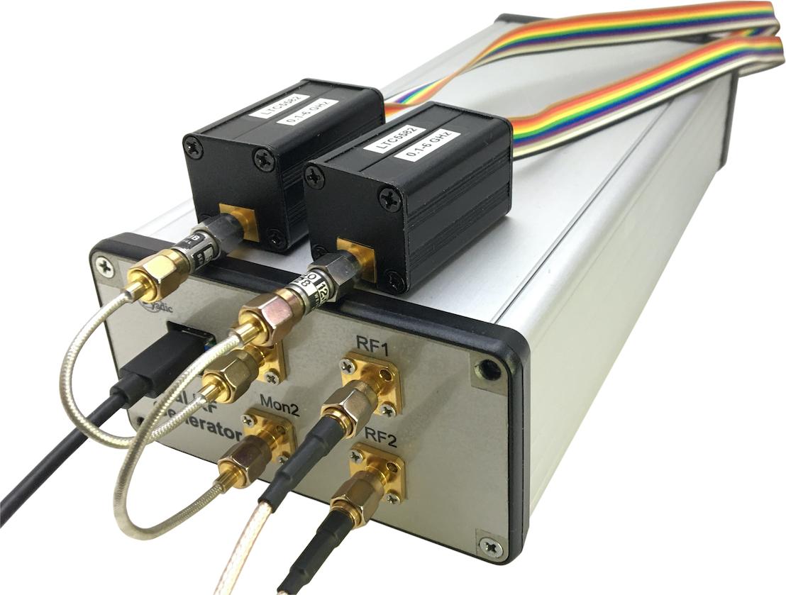
Figure 3: Output power control using power detectors on the monitor ports.
The signal generator uses a resistive bridge coupler on each signal channel to provide a monitoring port in addition to the actual signal output. The measured power output on the monitoring port can be used to infer the signal power on the channel output port.
Given the power measured on the monitor port, the associated output signal power is calculated by using the coupling and insertion loss of the bridge coupler at the signal frequency. The default polynomial fits for insertion loss and coupling are used to calculate the coupling and insertion loss for a given signal frequency.
from rfblocks import BridgeCoupler

coupler = BridgeCoupler()

chan_id = 'Chan 1'
freq = 1200.0
chan_output_pwr = (rfgen.measure_power(chan_id, freq=freq) - coupler.coupling(freq)
                   + coupler.insertion_loss(freq))
The rfgen RPyC service provides a method, set_channel_output for
setting the output frequency and level of a signal generator channel. The
method requires that a calibrated power detector head is connected the
monitoring port of the channel signal output and uses the measured coupled
output power to adjust the signal level until it is within a given
threshold of the specified output level.
The following code shows how set_channel_output can be used to implement
a background thread which continuously adjusts the signal output level so
that it remains at the specified level.
import os
import sys
from threading import Thread, Event, Lock
import rpyc


def level_output(lock, event, rfgen, chan_id):
    while True:
        with lock:
            freq = output_freq
            lvl = output_lvl
        if not rfgen.set_channel_output(chan_id, freq, lvl):
            print('Failed to set output level')
            break
        if event.is_set():
            print('level_output thread terminated')
            break


refdesigns_root = os.environ['RFBLOCKS_REFDESIGNS']
cal_file = f'{refdesigns_root}/PowerMeter/app/cal-files/24dB-atten-48-0007-Det3-100-6000MHz.json'
rfgen = rpyc.connect('127.0.0.1', 18864)
rfgen.root.initialize()
chan_id = 'Chan 1'
if not rfgen.root.initialize_detector(chan_id):
    print(f"Failed to initialize power detector for '{chan_id}'")
    sys.exit(-1)
det = rfgen.root.detector(chan_id)
if det is not None:
    det.load_caldata(cal_file)
    det.apply_correction = True
    det.avg = 4
else:
    print(f"Can't access power detector for '{chan_id}'")
    sys.exit(-2)

lock = Lock()
stop_event = Event()
output_freq = 1500.0
output_lvl = 0.0

level_thread = Thread(
    target=level_output,
    args=(lock, stop_event, rfgen.root, chan_id))
level_thread.start()

with lock:
    output_freq = 1200.0
    output_lvl = -5.0

# Stop the level thread
stop_event.set()

# Wait for the level thread to complete
level_thread.join()
The code does the following:
Import the required Python threading classes and the RPyC module.
Define a function to be executed as a separate thread which continually mesaures the channel signal output and adjusts the level to keep it at or near the specified signal output power.
Connect to the signal generator RPyC service.
Define some global variables. Specifically, a mutex
Lockand threadingEventinstance.Create a separate thread to run the
level_outputfunction in the background and start it.Signal output frequency and level are specified using the
output_freqandoutput_lvlvariables taking care to use the mutexLockin order to synchronize access with the levelling thread.When it is required to stop the background levelling thread the
stop_eventinstance is set and the main thread then waits for the levelling thread to complete and join the main thread.
Design Notes
Figure 4: RF generator schematic design.
The PLO module hardware is configured with no power splitter and therefore with one channel only active. The single channel is equipped with a SKY65017 output amplifer.
Figure 5: RF generator output power. The solid curves are for channel RF1, the dash curves are for RF2.
Figure 6: Maximum linear output power. The solid curve is for channel RF1, the dashed curve for channel RF2.
Figure 7: Simple RFGen channel cross talk.
Assembly
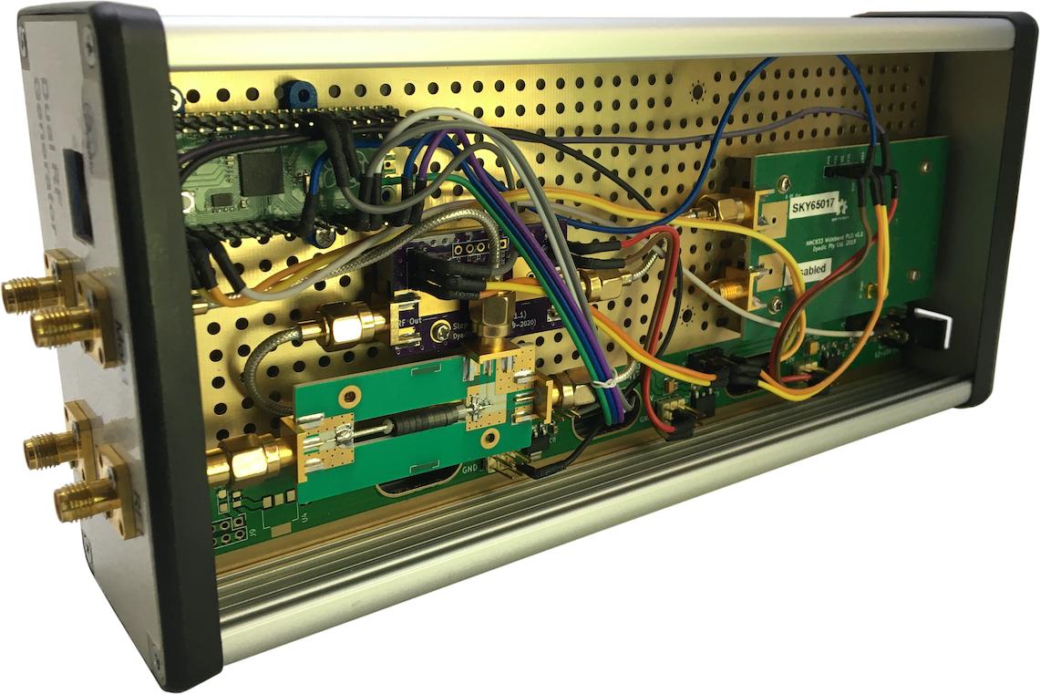
Figure 8a: Top side of assembly.
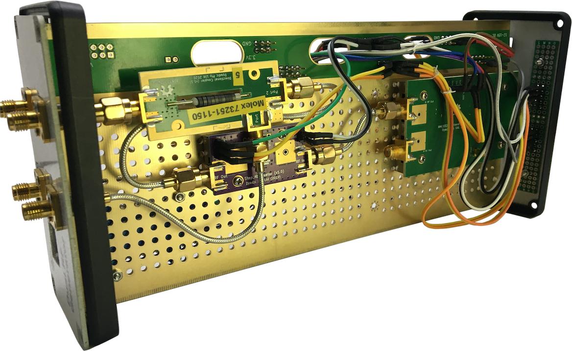
Figure 8b: Reverse side of assembly.
Calibration
For a specified frequency the output power on a signal generator channel is determined by setting the buffer gain value of the PLO module together with a step attenuation value. In order to determine the correct buffer gain value the power level generated by the associated PLO module must have been measured before hand. This is done using the calibration process described here.
Applying calibration data
Calibration measurements are contained in one set of dictionaries for each of the signal generator channels.
Measuring calibration data
Calibration measurements are made using the dual channel power meter. Because of this, the measured power levels will be the integrated power of the output signal. This will include the power in any harmonics present in the signal as well as the integrated noise out to the bandwidth of the power detector. The synthesizer has a low noise floor (typically -160 dBm) and therefore the integrated noise is negligible in this application. For low frequencies (< 500MHz) an appreciable amount of harmonic power is present. Depending on the application this may need to be corrected for when the signal generator is in use.
The RFBLOCKS_REFDESIGNS environment variable needs to be set to the
directory which holds the local rfblocks reference design git repos.
It takes about an hour to complete a calibration measurement run.
Figure 9a: Dual RF signal generator calibration setup schematic.
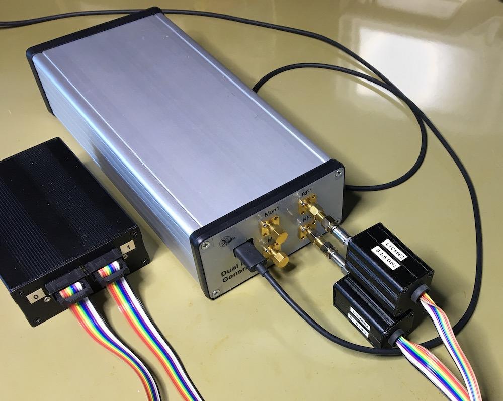
Figure 9a Dual RF signal generator calibration physical setup.
The Signal Generator App Source Code
A full description and code for the signal generator app is given here: rfgen.py.
Scripts
Output power calibration
-
Output power calibration script.
-
Initialize signal generator
try:
    rfgen = rpyc.connect("127.0.0.1", 18864)
except ConnectionRefusedError:
    print("Can't connect to the rfgen app. Is it running?")
    sys.exit(-1)
rfgen.root.initialize()
rfgen_chan_list = ['Chan 1', 'Chan 2']
for chan_id, chan in rfgen.root.channels.items():
    chan.atten_ctl.attenuation = 0.0
    rfgen.root.configure_atten(chan_id)
    chan.plo_ctl.vco_mute = False
rfgen.root.set_calibration_mode(True)
-
Initialize the power meter. Note that 24 dB attenuators are connected between the RF generator signal outputs and the power meter measurement heads. Calibration data files for these attenuators (generated separately) are loaded explicitly.
pwr_app_path = Path(
    os.path.expandvars('${RFBLOCKS_REFDESIGNS}/PowerMeter/app'))

# The power meter is set up with measurement head 'Det 3' (on power
# meter channel 0) connected to RF generator output 'RF1' via the
# 48-0007 24 dB attenuator.  Measurement head 'Det 4' (on power
# meter channel 1) connected to generator output 'RF2' via the
# 48-0008 24 dB attenuator.
chan0_cal_file = 'cal-files/24dB-atten-48-0007-Det3-100-6000MHz.json'
chan1_cal_file = 'cal-files/24dB-atten-48-0008-Det4-100-6000MHz.json'
try:
    pwrmeter = rpyc.connect("127.0.0.1", 18863)
except ConnectionRefusedError:
    print("Can't connect to the pwrmeter app. Is it running?")
    sys.exit(-1)
pwrmeter.root.initialize()
pwr_detectors = [0, 1]
detector_cal_files = [chan0_cal_file, chan1_cal_file]
for det, cal_file in zip(pwr_detectors, detector_cal_files):
    cal_file_path = str(pwr_app_path / cal_file)
    print(f'{cal_file_path=}')
    pwrmeter.root.detectors[det].load_caldata(cal_file_path)
    pwrmeter.root.detectors[det].apply_correction = True
-
Measure output power as a function of frequency.
<<max-linear-gains>>

def measure_max_linear_pwr(rfgen, rfgen_chan,
                           pwrmeter, det, freq_list):
    sig_pwr = {}
    chan = rfgen.root.channels[rfgen_chan]
    for f in freq_list:
        chan.plo_ctl.freq = f
        buf_gain = max_linear_gain(f)
        chan.plo_ctl.buffer_gain = int(buf_gain)
        rfgen.root.configure_plo(rfgen_chan)
        pwrmeter.root.detectors[det].freq = f
        pwrmeter.root.measure(det)
        pwr = pwrmeter.root.detectors[det].pwr
        sleep(0.2)
        sig_pwr['{:.1f}'.format(f)] = float(pwr)
    return sig_pwr

def measure_integrated_pwr(rfgen, rfgen_chan,
                           pwrmeter, det, freq_list):
    sig_pwr = {}
    chan = rfgen.root.channels[rfgen_chan]
    for f in freq_list:
        chan.plo_ctl.freq = f
        try:
            rfgen.root.configure_plo_freq(rfgen_chan)
        except TimeoutError as te:
            # Retry
            print(te)
            rfgen.root.configure_plo_freq(rfgen_chan)
        pwrmeter.root.detectors[det].freq = f
        pwrmeter.root.measure(det)
        try:
            pwr = pwrmeter.root.detectors[det].pwr
        except TimeoutError as te:
            # Retry
            print(te)
            pwr = pwrmeter.root.detectors[det].pwr
        sleep(0.2)
        sig_pwr['{:.1f}'.format(f)] = float(pwr)
    return sig_pwr
linear_gains = {
    25: hmc833.OutputBufferGain.MAXGAIN,
    150: hmc833.OutputBufferGain.MAXGAIN_MINUS_3DB,
    200: hmc833.OutputBufferGain.MAXGAIN_MINUS_6DB,
    1200: hmc833.OutputBufferGain.MAXGAIN_MINUS_3DB,
    1500: hmc833.OutputBufferGain.MAXGAIN_MINUS_6DB,
    2000: hmc833.OutputBufferGain.MAXGAIN_MINUS_3DB,
    3000: hmc833.OutputBufferGain.MAXGAIN,
    6000: hmc833.OutputBufferGain.MAXGAIN
}

def max_linear_gain(f):
    i = 0
    freqs = list(linear_gains.keys())
    while i < len(freqs):
        if f > freqs[i]:
            i += 1
        else:
            k = max(0, i-1)
            gain = list(linear_gains.values())[k]
            break
    return gain
-
Measure output power for each gain setting.
def main():

    defaultOutputFile = 'rfgen-output-power.json'

    parser = ArgumentParser(description=
                            '''Calibrate dual RF signal generator''')
    parser.add_argument(
        "-O", "--output_file", default=defaultOutputFile,
        help=f"File to write measured output powers.  "
        f"Default: {defaultOutputFile}"
    )
    parser.add_argument(
        "-M", "--max_linear_gain", action='store_true',
        help="Measure output power for maximum linear gain settings."
    )
    args = parser.parse_args()

    <<initialize-rfgen>>

    <<initialize-pwrmeter>>

    # Insert more cal. points in and around areas of abrupt power
    # level changes.
    freq_list = [float(f) for f in np.linspace(100.0, 6000.0, 100).round()]
    freq_list.extend([1442, 1452, 1462, 1472, 1482, 1499, 1500, 1512,
                      1522, 1532, 1542, 1562, 1572, 1582, 1592])
    freq_list.extend([2945, 2955, 2965, 2975, 2985, 3000, 3001, 3015,
                      3025, 3035, 3045])
    freq_list.sort()

    divider_gain = hmc833.DividerGain.MAXGAIN_MINUS_3DB
    buffer_gain_settings = {
        'max-minus-9dB': hmc833.OutputBufferGain.MAXGAIN_MINUS_9DB,
        'max-minus-6dB': hmc833.OutputBufferGain.MAXGAIN_MINUS_6DB,
        'max-minus-3dB': hmc833.OutputBufferGain.MAXGAIN_MINUS_3DB,
        'maxgain': hmc833.OutputBufferGain.MAXGAIN}

    chans = rfgen.root.channels
    for rfgen_chan in rfgen_chan_list:
        chans[rfgen_chan].plo_ctl.divider_gain = divider_gain
        rfgen.root.configure_plo(rfgen_chan)

    if args.max_linear_gain is True:
        output_pwr = {
            "linear_gains": linear_gains,
            'Chan 1': {},
            'Chan 2': {} }
        for rfgen_chan, pwr_det in zip(rfgen_chan_list, pwr_detectors):
            output_pwr[rfgen_chan] = measure_max_linear_pwr(
                rfgen, rfgen_chan, pwrmeter, pwr_det, freq_list)
    else:
        output_pwr = { 'Chan 1': {}, 'Chan 2': {} }
        for label, gain in buffer_gain_settings.items():
            for rfgen_chan, pwr_det in zip(rfgen_chan_list, pwr_detectors):
                print(f'{rfgen_chan=}, {label=}, {gain=}')
                chans[rfgen_chan].plo_ctl.buffer_gain = gain
                rfgen.root.configure_plo(rfgen_chan)
                output_pwr[rfgen_chan][label] = measure_integrated_pwr(
                    rfgen, rfgen_chan, pwrmeter, pwr_det, freq_list)

    with open(args.output_file, 'w') as fd:
        json.dump(output_pwr, fd)

    for chan_id, chan in rfgen.root.channels.items():
        chan.plo_ctl.vco_mute = True
    rfgen.root.set_calibration_mode(False)
Format measured calibration data
import json
from argparse import ArgumentParser
import numpy as np


def format_cal_data_dict(cd_dict):
    cols = 4
    sd = [f'{f}: {float(p):.2f},' for f, p in cd_dict.items()]
    output_str = '\n'.join([''.join(['        '] + [f'{ls: <16}'
                            for ls in lst[:-1]] + [f'{lst[-1]}'])
                            for lst in [sd[i:i+cols]
                                        for i in range(0, len(sd), cols)]])
    return output_str


def format_chan_cal_data(chan_dict):
    output_str = '\n'.join([f"    '{k}': {{\n{format_cal_data_dict(cd_dict)}\n    }},"
                            for k, cd_dict in chan_dict.items()])
    return output_str


def read_cal_data(data_files):

    with open(data_files[0]) as fd:
        cal_data = json.load(fd)

    if len(data_files) > 1:
        # Read all the files and generate averages for the
        # measured signal powers.
        cal_data_list = [cal_data]
        for data_file in data_files[1:]:
            with open(data_file) as fd:
                cal_data_list.append(json.load(fd))
        chan_arrays = {}
        for data in cal_data_list:
            for chan_id, chan_dict in data.items():
                if chan_id in chan_arrays:
                    pwr_arrays = chan_arrays[chan_id]
                else:
                    pwr_arrays = {}
                    chan_arrays[chan_id] = pwr_arrays
                for gain_label, cd_dict in chan_dict.items():
                    parr = np.array([p for p in cd_dict.values()])
                    if gain_label in pwr_arrays:
                        pwr_arrays[gain_label] += parr
                    else:
                        pwr_arrays[gain_label] = parr
        for chan_id, chan_array in chan_arrays.items():
            for gain_label, pwr_array in chan_array.items():
                # Replace pwr values in cal_data with the averages
                # computed from pwr_array
                parr = chan_arrays[chan_id][gain_label] / len(data_files)
                cal_data[chan_id][gain_label] = {
                    fs: p for fs, p in zip(cal_data[chan_id][gain_label], parr)}

    return cal_data


def main(cal_data_files):

    cal_data = read_cal_data(cal_data_files)

    print('CHAN1_CAL_DATA = {')
    print(format_chan_cal_data(cal_data['Chan 1']))
    print('}')
    print('CHAN2_CAL_DATA = {')
    print(format_chan_cal_data(cal_data['Chan 2']))
    print('}')

if __name__ == '__main__':

    defaultInputFile = 'rfgen-output-power.json'

    parser = ArgumentParser(description=
                            '''Format RF signal generator calibration data''')
    parser.add_argument(
        "-I", "--input_files", default=[defaultInputFile], nargs='+',
        help=f"File containing calibration data as written by"
        " the rfgen-calibrate.py script."
        f" Default: {defaultInputFile}"
    )
    args = parser.parse_args()

    main(args.input_files)
Insertion loss and coupling curve fits
from pathlib import Path
import skrf as rf
from skrf import Network, Frequency
import numpy as np
import matplotlib.pyplot as plt
from scipy.optimize import curve_fit
from dyadic.splot import init_style

def linear_func(x, a, b):
    return a*x + b

annotation_color = 'darkgrey'
freq_range = '10-6000mhz'
dataPath = Path(data_path)
ntwk = Network(str(dataPath / s12_file))[freq_range]
popt, perr = curve_fit(linear_func, ntwk.f/1e6, ntwk.s21.s_db[:,0,0])
print("coeffs: {},\nerrors: {}".format(popt, perr))
init_style()
fig = plt.figure(num=None, figsize=(6.0, 4.0), dpi=72)
ax = fig.add_subplot(111)
_ = ax.set_ylim(-4.0, -1.0)
_ = ax.set_xlim(0.0, 6000.0)
_ = ax.set_xlabel('Frequency (MHz)')
_ = ax.set_ylabel('Loss (dB)')
ax.grid(linestyle=':')
ax.grid(which='both', axis='x', linestyle=':')
ax.set_title('Insertion Loss Curve Fit')
ax.plot(ntwk.f/1e6, ntwk.s21.s_db[:,0,0])
ax.plot(ntwk.f/1e6, [linear_func(f, *popt) for f in ntwk.f/1e6],
        linestyle='dashed')
fig.tight_layout()
plt.savefig(outfile)
from pathlib import Path
import skrf as rf
from skrf import Network, Frequency
import numpy as np
import matplotlib.pyplot as plt
from scipy.optimize import curve_fit
from dyadic.splot import init_style

def poly_func(x, a, b, c, d, e, f, g):
    return (((((a*x + b)*x + c)*x + d)*x + e)*x + f)*x + g

annotation_color = 'darkgrey'
freq_range = '10-6000mhz'
dataPath = Path(data_path)
ntwk = Network(str(dataPath / s23_file))[freq_range]
popt, perr = curve_fit(poly_func, ntwk.f/1e6, ntwk.s21.s_db[:,0,0])
print("coeffs: {},\nerrors: {}".format(popt, perr))
init_style()
fig = plt.figure(num=None, figsize=(6.0, 4.0), dpi=72)
ax = fig.add_subplot(111)
_ = ax.set_ylim(-18.0, -15.0)
_ = ax.set_xlim(0.0, 6000.0)
_ = ax.set_xlabel('Frequency (MHz)')
_ = ax.set_ylabel('Coupling (dB)')
ax.grid(linestyle=':')
ax.grid(which='both', axis='x', linestyle=':')
ax.set_title('Coupling Curve Fit')
ax.plot(ntwk.f/1e6, ntwk.s21.s_db[:,0,0])
ax.plot(ntwk.f/1e6, [poly_func(f, *popt) for f in ntwk.f/1e6],
        linestyle='dashed')
fig.tight_layout()
plt.savefig(outfile)