Dual Channel RF Power Meter Designs
Usage
The power meter consists of two power detector 'heads'. Depending on the frequency response requirements of measurements, these heads may contain either an LTC5582 RF detector board or an LT5537 detector board. Power and SPI connections for the detector heads are taken from a small enclosure containing the controller which is connected to a host computer via USB.
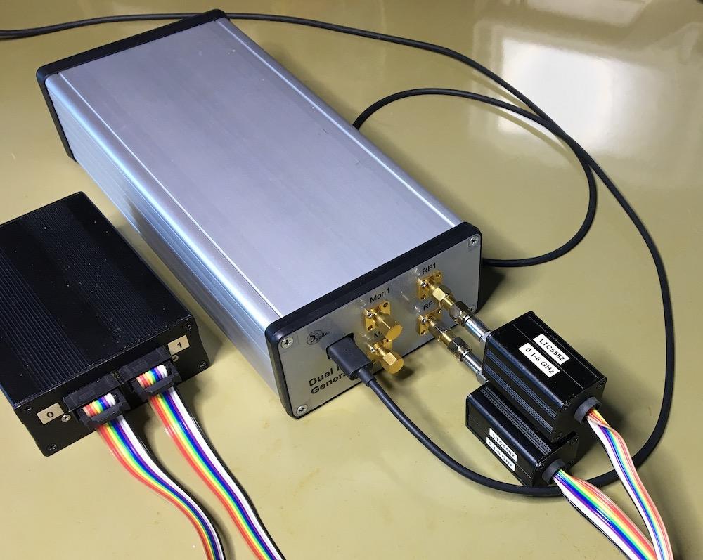
Figure 1 A power meter calibrating a dual RF signal generator.
Initialization
At startup the USB/RS232 serial control port associated with the
power meter app is selected from the Control Port drop down menu.
The power meter app is then configured for use with the hardware by
selecting the Initialize button.
The initialization process first initializes the power detectors connected to the power meter. This includes loading the detector hardware calibration information. After hardware initialization the app on screen UI is initialized and enabled.
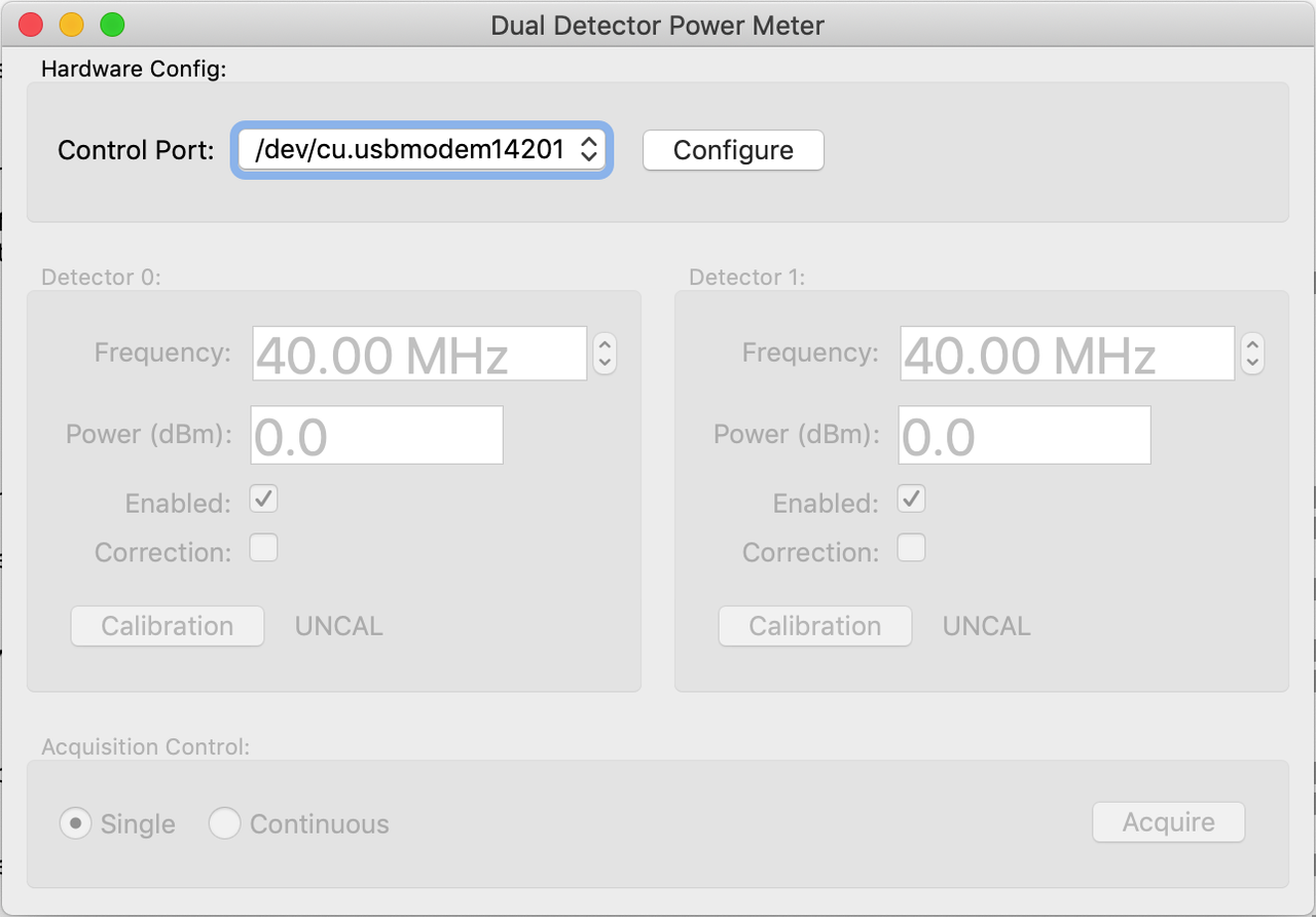
Figure 2: Power meter at startup
Configuration
After initialization both power meter detectors are available for use. An unused detector can be disabled if desired although this isn't absolutely necessary. Disabling a detector will disable the associated user interface controls.
Measurements are taken by first entering the signal frequency and
then selecting the Acquire button. By default this will carry out
a single signal power measurement on each enabled detector.
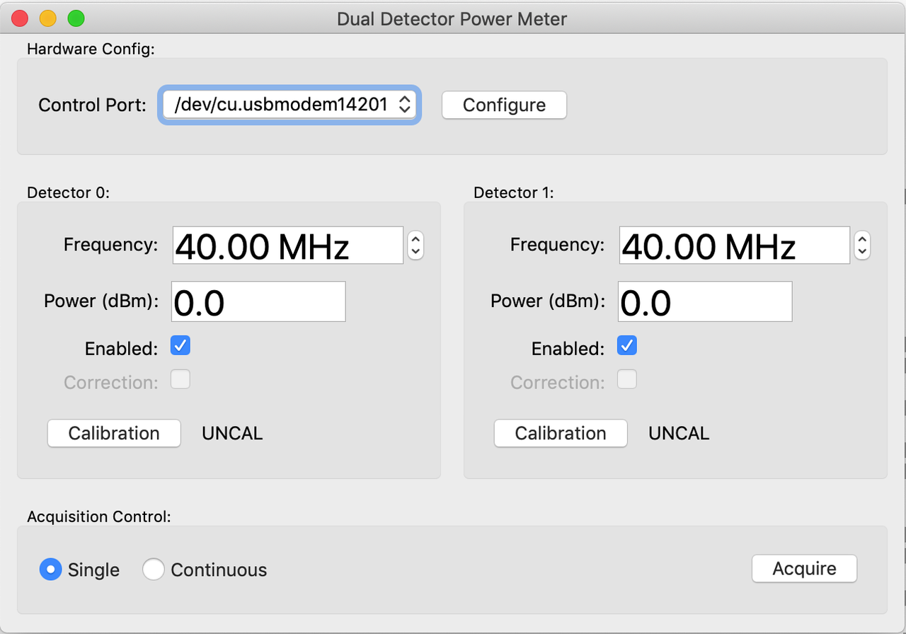
Figure 3: Power meter configured
Continuous signal power measurements are enabled by selecting the
Continuous button in the Acquisition Control panel and then
selecting Acquire. Power measurements will now be continuously
taken for each enabled detector until the Stop button is selected.

Figure 4: Power meter continuous acquisition
Calibration and correction
In general, power detectors will be connected to the device under
test via some intermediate set of cabling and other devices. For
example, if the expected signal power to be measured is outside the
linear range of the detector then either attenuation or amplification
must be included. Similarly, cable losses must be corrected. What
is required is for the calibration plane of the detector to be moved
from the detector's connector to the connector which is mated with
the device under test. Initially, the power detectors are in the
UNCAL state as shown by the calibration state indicator next to the
Calibration button.
In order to generate calibration data for a given measurement setup,
the Detector Calibration facility may be accessed by selecting the
Calibration button associated with the detector in question.
Calibration data may either be loaded from a previously saved data
set or generated using a known signal source.
Figure 5: Typical power meter calibration setup
The detector, including any intermediate cables, connectors,
attenuation or amplifiers should be connected to a signal generator
which covers the frequency range of interest. A suitable signal
source power is entered together with the range of frequencies
covering the measurements which will be taken. Selecting the
Calibrate button now generates the required calibration data. This
data may optionally be saved to a file.
Once the app has access to valid calibration data the calibration
state indicator for the detector will change to INCAL.
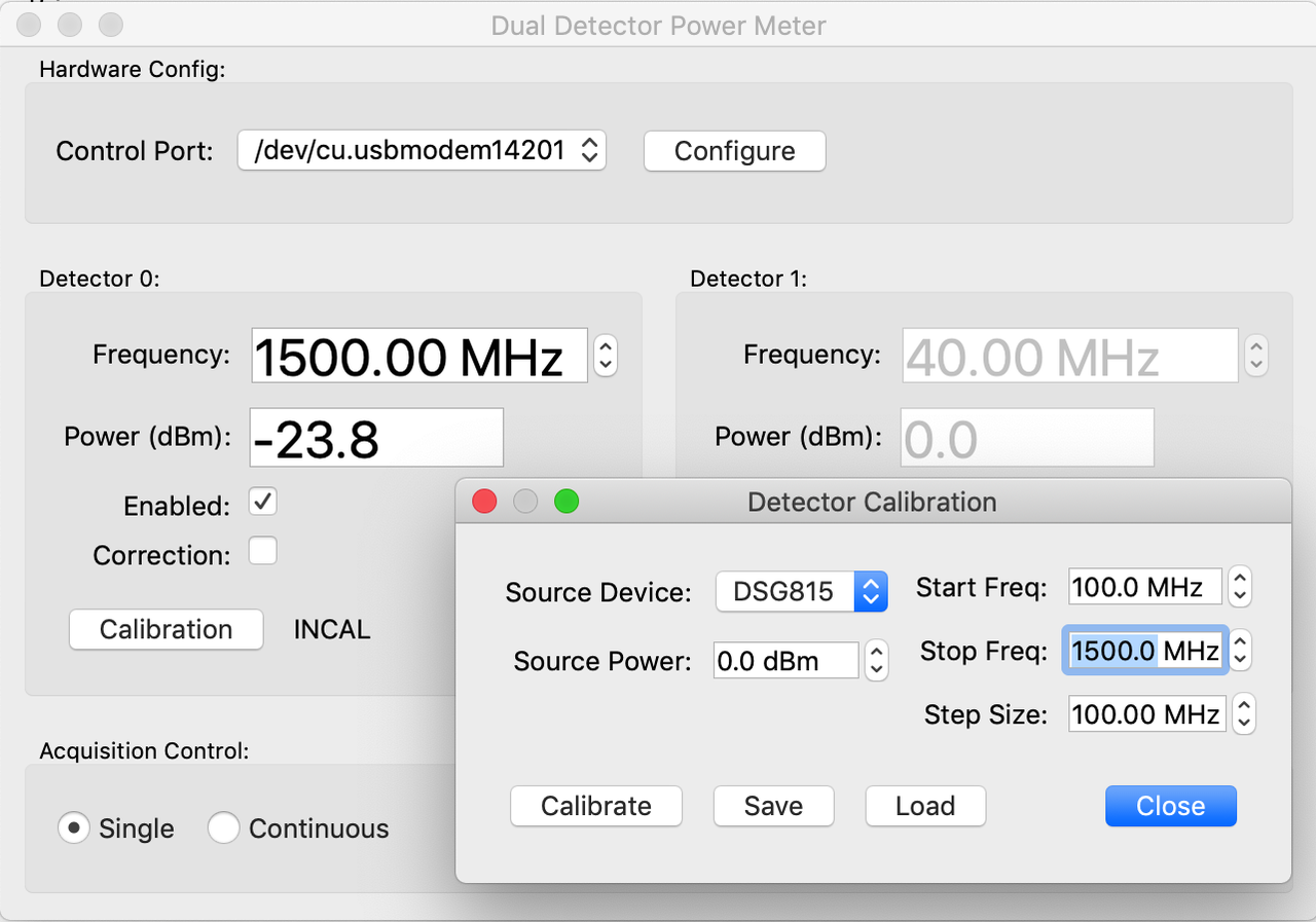
Figure 6: Power meter detector calibration
To make use of calibration data to apply corrections to detector
power measurements, select the Correction check box. All power
measurements acquired by the associated detector will now have a
correction applied before being displayed. Note that if a signal
frequency outside the valid calibration range is entered the
calibration indicator will change to UNCAL and corrections will not
be applied.
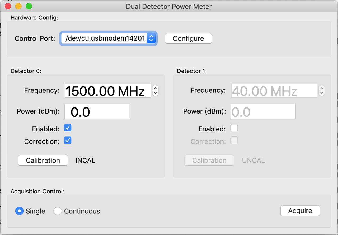
Figure 7: Power meter using calibrated correction
Generating calibration data from S-parameter measurements
Measurements
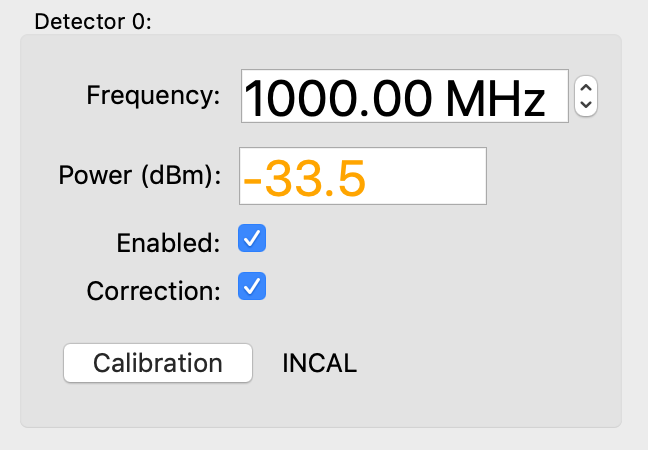
Power detector measurement within 0.5dB of non-linear region
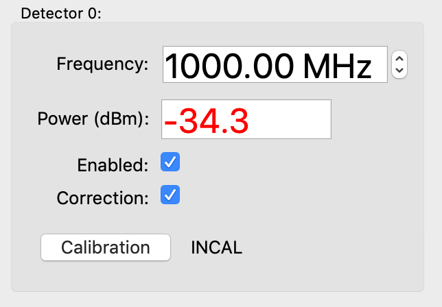
Power detector measurement is in non-linear region
Extending the power measurement range
Software control
Software control of the power meter is done via the PwrMeterService
RPyC service provided by the power meter reference design app. The
service API is given here: The pwrmeter Service.
Before running the rpyc client example code below the power
detector app should be started:
Note that the command serial device must either be specified on the
command line as above or selected from the Control Port drop down list
once the app is running and displayed on-screen. If the app is run
'headless' (by specifying the '--nogui' command line option) then the
serial device must also be specified via the command line.
By default the pwrmeter service will listen on port 18863 of
the localhost interface. This may be changed by using the -P and -A
command line options when starting the app.
import rpyc
from tam import DSG815_ID

pwrmeter = rpyc.connect('127.0.0.1', 18863)
pwrmeter.root.initialize()
chan_controllers = pwrmeter.root.detectors
chan_ctl0 = chan_controllers[0]
chan_ctl1 = chan_controllers[1]

# Calibration is a long running process and the calibrate call
# is synchronous.  The rpyc request timeout should be either
# disabled or set to a long period so that a timeout isn't triggered
old_timeout = pwrmeter._config['sync_request_timeout']
pwrmeter._config['sync_request_timeout'] = None
status = pwrmeter.root.calibrate(0, 'DSG815', DSG815_ID, 0, 0.0, 100.0, 1500.0, 100.0)
pwrmeter.root.calstatus[0]   # should return 0

# Restore the rpyc request timeout value
pwrmeter._config['sync_request_timeout'] = old_timeout

chan_ctl0.freq = 500.0
pwrmeter.root.measure(0)
pwr = chan_ctl0.pwr
chan_ctl0.apply_correction = True
pwrmeter.root.measure(0)
corrected_pwr = chan_ctl0.pwr

chan_ctl1.freq = 150.0
pwrmeter.root.measure(1)
pwr = chan_ctl1.pwr

pwrmeter.close()
Design Notes
Figure 8: Power meter schematic design.
Assembly
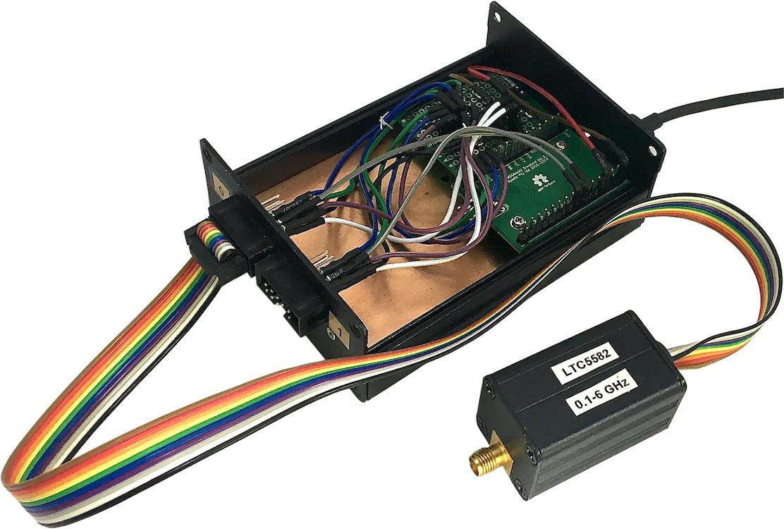
Figure 9a: Power meter assembly
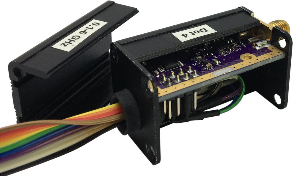
Figure 9b: Power head assembly
The Power Meter App Source Code
A full description and code for the power meter app is given here: pwrmeter.py.