A DDS Based Signal Generator
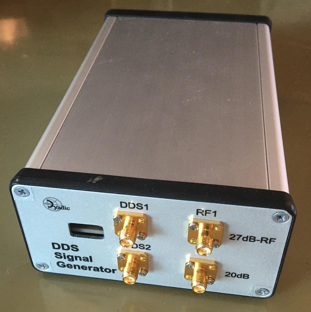
DDS Signal Generator - Front
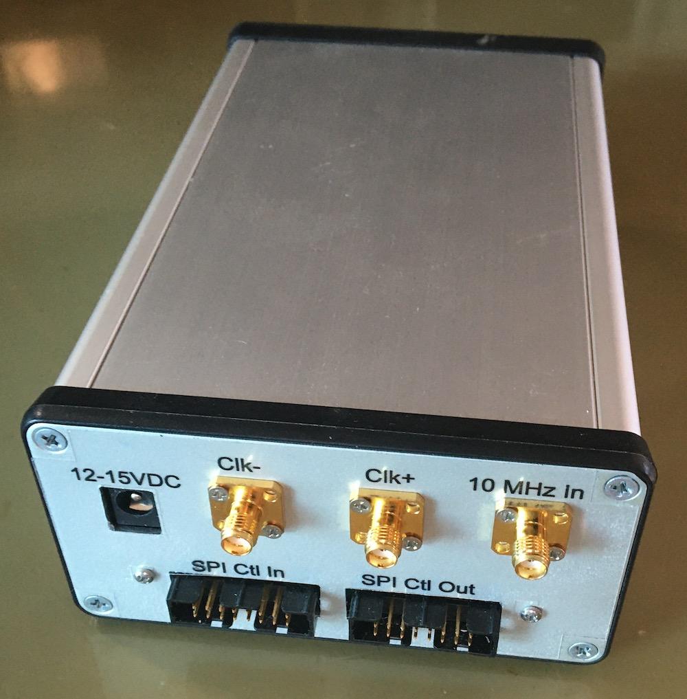
DDS Signal Generator - Back
Hardware Setup
Two DDS signal channels are available. On the front panel, SMA connectors
marked DDS1 and RF1 are outputs for the first DDS channel and the SMA
connector marked DDS2 is the single output for the second channel.
The front panel also provides access to the controller USB connector.
Note that if only one of the DDS1 or RF1 outputs are used the other
should be terminated with a 50 ohm load.
On the rear of the enclosure, SMA connectors for Clk1- and Clk1+ are outputs
of the auxiliary DDS clock and an input for a 10 MHz external reference.
There is also the input for 12 to 15VDC power and connectors for daisy chaining
SPI and GPIO signals.
Application Usage
The DDSGen app is started from the command line. If the app is started
without specifying a serial device (using the -d option) a list of
suitable connected devices will be presented in the Control Port drop
down in app UI.
or
The app may also be started from the app launcher if this is configured and running.
Once running the app is used as follows:
Select the signal generator hardware control port. This is only necessary when the USB control port device has not been specified either on the command line of via the app launcher.
Initialize the signal generator hardware by selecting the
InitializeUI button.Optionally, select the signal generator reference source. If an external reference is being used this must be a 10MHz source connected to the
10MHz InSMA connector on the rear of the signal generator.The DDS channels can now be configured using the relevant Channel controls.
Figure 1: DDS signal generator app
Other controls at the bottom of the app window are:
Two Tone...-
Display the Two Tone Settings dialog. This allows the quick configurtion of the two DDS channels for two tone signal generation.
Sync-
Synchronize the phases of the two DDS channels. This allows for a differential phase setting between the two DDS channel output signals.
Enable Aux. Clk-
When checked this enables the controls of the clock generator used for both the DDS and the two clock outputs on the rear of the signal generator enclosure. This can, for example, be used to adjust the DDS reference clock frequency. Some caution should be exercised here.
Command line usage:
usage: ddsgen.py [-h] [--nogui] [-d DEVICE] [-b BAUDRATE] [-A IPADDR] [-P PORT] [-H] [-F REFFREQ] [--dds1model DDS1MODEL]
                 [--dds2model DDS2MODEL]

A DDS signal generator.

optional arguments:
  -h, --help            show this help message and exit
  --nogui               Disable GUI and run 'headless'
  -d DEVICE, --device DEVICE
                        The hardware serial device
  -b BAUDRATE, --baudrate BAUDRATE
                        Baud rate (default: 0)
  -A IPADDR, --ipaddr IPADDR
                        IP address for to bind the RPyC server instance
  -P PORT, --port PORT  TCP port for the RPyC server instance
  -H, --dumphw          Dump device hardware config to stdout and exit
  -F REFFREQ, --reffreq REFFREQ
                        Clock reference frequency (in MHz). Default: 10MHz
  --dds1model DDS1MODEL
                        Board variant model for DDS chan 1. Default: 27dB-RF
  --dds2model DDS2MODEL
                        Board variant model for DDS chan 2. Default: 20dB
Channel controls
The usual frequency, phase and level controls are available. The level
control allows for the level units to be selected via a drop down list.
On entering the desired values the DDS channel hardware is updated using
the Configure button.
Figure 2: DDS signal generator channel controls
Other available controls are:
Pogrammable Modulus-
When this is checked the programmable modulus mode of the AD9913 is used to provide an exact frequency output. For further details see the Programmable Modulus Mode section on p 14 of the Rev. D AD9913 datasheet and Direct Digital Synthesis (DDS) with a Programmable Modulus.
Active-
When checked the DDS channel signal output is enabled. When un-checked the signal output is muted.
Sweep...-
Displays the channel sweep settings.
Profiles...-
Displays the channel profile settings.
Profiles
The channel profile settings allow the configuration and use of profile selections and direct switch mode as documented in the AD9913 datasheet (Profile Selections on p13 and Direct Switch Mode on p14 of the Rev. D AD9913 datasheet).
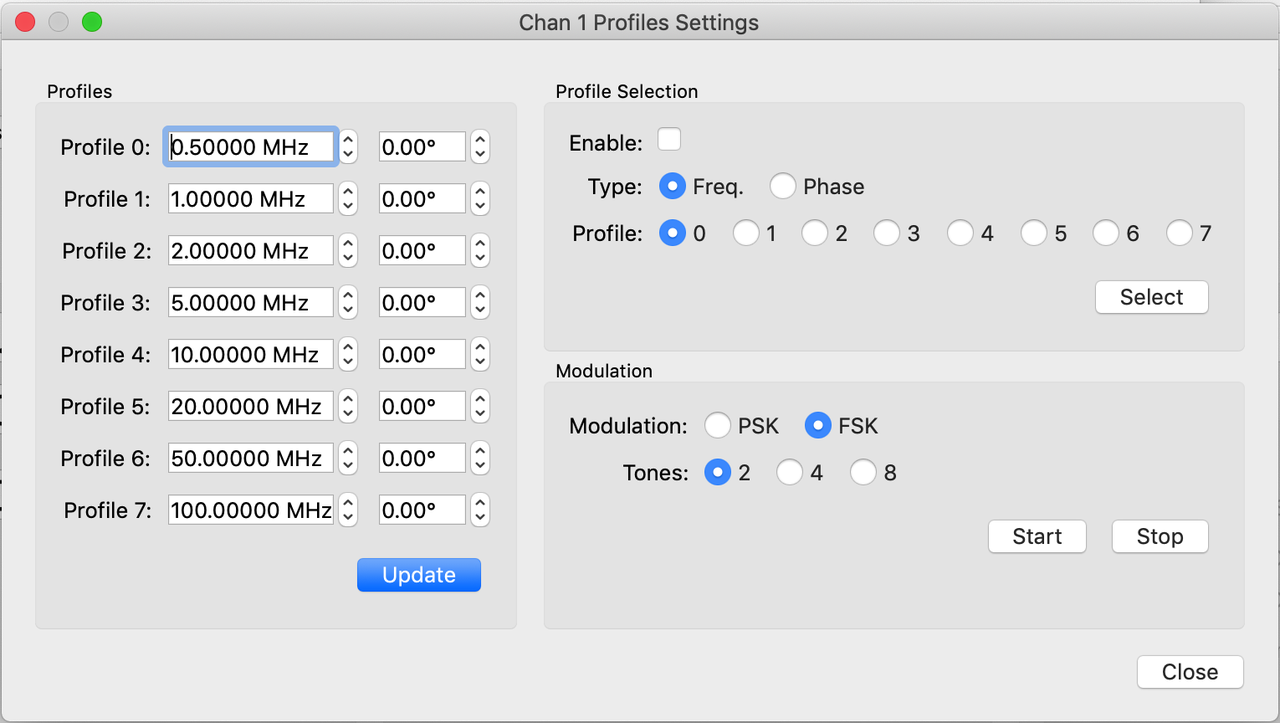
Figure 3: Channel profiles
Sweeping
The channel sweep settings allows the configuration of simple frequency and phase sweeps as documented in the AD9913 datasheet (Linear Sweep Mode section on pages 14 to 16 of the Rev. D AD9913 datasheet).
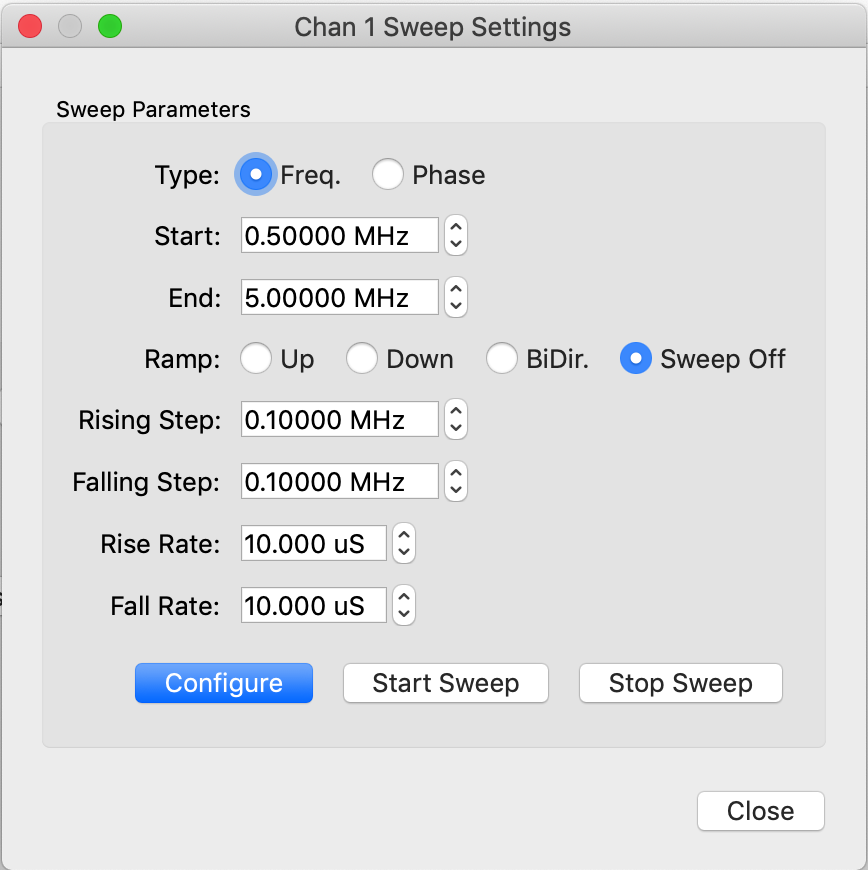
Figure 4: Sweeping
Typical Characteristics
Typical characteristics of the DDS signals are given in the AD9913 DDS module documentation.
Software control
This section illustrates the use of an rpyc client for the DDS signal
generator. Before running the example code below the signal generator app
should be started, see Application Usage.
If the app is run 'headless' (by specifying the '--nogui' command line
option) then the control serial device must also be specified via the
command line. By default the ddsgen service will listen on port 18862 of
the localhost interface. This may be changed by using the -P and -A
command line options when starting the app.
>>> import rpyc
>>> from rfblocks import ad9913

>>> ddsgen = rpyc.connect("127.0.0.1", 18862)
>>> ddsgen.root.initialize()
>>> dds1 = ddsgen.root.dds_controllers['Chan 1']
>>> dds2 = ddsgen.root.dds_controllers['Chan 2']

>>> dds2.state = ad9913.POWER_UP
>>> dds2.freq = 25.0
>>> dds2.dbm = 0.0
>>> ddsgen.root.configure('Chan 2')

>>> dds1.state = ad9913.POWER_UP
>>> dds1.freq = 25.0
>>> dds1.dbm = 0.0
>>> ddsgen.root.configure('Chan 1')
The code above does the following:
Import the
rpycmodule and therfblocksad9913class.Connect to the DDSGenService
rpycservice. This assumes that the DDSGen app is running on the default port, 18862.Initialize the service.
Create two variables holding references to the two AD9913Controller instances.
Set the state of the second channel controller and configure it. This will set the output frequency to 25 MHz, the output power to 0 dBm and power up the channel.
Set the state of the first channel control and configure it Similarly.
>>> dds2._ad9913.cfr1 = ad9913.DEFAULT_CFR1
>>> dds2.sweep_start = 20.0
>>> dds2.sweep_end = 30.0
>>> dds2.sweep_type = ad9913.SweepType.FREQUENCY
>>> dds2.sweep_ramp_type = ad9913.SweepRampType.RAMP_BIDIR
>>> dds2.sweep_rising_step = 0.001
>>> dds2.sweep_falling_step = 0.001
>>> dds2.sweep_rising_rate = 256
>>> dds2.sweep_falling_rate = 256
>>> ddsgen.root.configure_sweep('Chan 2')
>>> ddsgen.root.start_sweep('Chan 2')
The code above continues the example by initiating a sweep of output frequency:
Reset the control function register to the default.
Set the start and end output frequencies for the sweep to 20 and 30 MHz respectively.
Set the sweep type to be across frequency and to be bidirectional. This means the signal will traverse up and down the specified frequecy range.
The sweep step and rate are set so that the progress of the output signal as it traverses the sweep frequency range is easily observable on a spectrum analyzer or oscilloscope.
The
configure_sweepmethod pushes the sweep state to the DDS registers.The actual sweep process is started by calling the
start_sweepmethod with the sweep continuing until thestop_sweepmethod is called.
>>> dds2.direct_switch_enabled = True
>>> dds2.profile_type = ad9913.SweepType.FREQUENCY
>>> dds2.set_profile_freq(0, 25.0)
>>> dds2.set_profile_freq(1, 35.0)
>>> ddsgen.root.update_profile('Chan 2', 0)
>>> ddsgen.root.update_profile('Chan 2', 1)
>>> dds2.selected_profile = 0
>>> ddsgen.root.configure_profile('Chan 2')
>>> dds2.selected_profile = 1
>>> ddsgen.root.configure_profile('Chan 2')
>>> dds2.selected_profile = 0
>>> ddsgen.root.configure_profile('Chan 2')
>>> dds2.direct_switch_enabled = False
Extending the code further:
Enable direct switch mode. This mode allows the direct update of either frequency or phase from the AD9913 profiles registers.
Set the profile type to be
FREQUENCY. When a direct update is made the DDS frequency will be configured from the selected profile frequency register.Set the profile frequency registers for profiles 0 and 1. Push the profile values to the DDS profile registers using the
AD9913Controllerupdate_profilemethod.Set a selected profile and update the DDS frequency from the associated profile register using the
configure_profileregister.
>>> dds2.state = ad9913.POWER_UP
>>> dds2.freq = 20.0
>>> dds2.dbm = 0.0
>>> ddsgen.root.set_pmod('Chan 2', True)
>>> ddsgen.root.configure('Chan 2')
Finally, set an output frequency of exactly 20 MHz using the AD9913 programmable modulus mode.
DDSGen service API
def initialize(self) -> None:
    """Initialize the signal generator hardware and software.

    >>> import rpyc
    >>> ddsgen = rpyc.connect("127.0.0.1", 18862)
    >>> ddsgen.root.initialize()

    """

@property
def dds_controllers(self):
    """A dictionary containing the signal generator DDS controllers.

    The controllers are instances of AD9913_Controller keyed using
    the channel identifiers 'Chan 1' and 'Chan 2' respectively.

    >>> import rpyc
    >>> ddsgen = rpyc.connect("127.0.0.1", 18862)
    >>> ddsgen.root.initialize()
    >>> dds1 = ddsgen.root.dds_controllers['Chan 1']
    >>> dds1
    <rfblocks.ad9913_controller.AD9913Controller object at 0x126f8b4c0>
    >>> dds2 = ddsgen.root.dds_controllers['Chan 2']

    """

@property
def clk_controller(self):
    """The controller for the DDS reference clock.

    An instance of AD9552_Controller.

    >>> import rpyc
    >>> ddsgen = rpyc.connect("127.0.0.1", 18862)
    >>> ddsgen.root.initialize()
    >>> refclk = ddsgen.root.clk_controller

    """

def configure(self, ctl_id):
    """Configure AD9913 DDS hardware registers for a specified channel.

    :param ctl_id: A channel id.  This will be one of "Chan 1" or "Chan 2".
    :type ctl_id: str

    >>> import rpyc
    >>> ddsgen = rpyc.connect("127.0.0.1", 18862)
    >>> ddsgen.root.initialize()
    >>> dds1 = ddsgen.root.dds_controllers['Chan 1']
    >>> dds1.freq = 25.0
    >>> dds1.dbm = -10.0
    >>> ddsgen.root.configure('Chan 1')
    """

def configure_sweep(self, ctl_id):
    """Configure AD9913 DDS sweep registers for a specified channel.

    :param ctl_id: A channel id.  This will be one of "Chan 1" or "Chan 2".
    :type ctl_id: str
    """

def update_profile(self, ctl_id, profnum):
    """Update AD9913 DDS profile registers for a specified channel and profile.

    :param ctl_id: A channel id.  This will be one of "Chan 1" or "Chan 2".
    :type ctl_id: str
    :param profnum: The AD9913 profile register to update.
    :type profnum: An integer in the range 0 to 7.
    """

def configure_profile(self, ctl_id):
    """
    """

def start_sweep(self, ctl_id):
    """Start an AD9913 sweep operation for a specified channel.

    :param ctl_id: A channel id.  This will be one of "Chan 1" or "Chan 2".
    :type ctl_id: str
    """

def stop_sweep(self, ctl_id):
    """Stop an AD9913 sweep operation.

    :param ctl_id: A channel id.  This will be one of "Chan 1" or "Chan 2".
    :type ctl_id: str
    """

def set_pmod(self, ctl_id: str, state: bool) -> None:
    """Set the DDS programmable modulus state.

    :param ctl_id: A channel id.  This will be one of "Chan 1" or "Chan 2".
    :type ctl_id: str
    :param state: Set to True in order to enable progammable modulus.
        False to disable it.
    :type state: bool

    Note that :py:meth:`configure` must be invoked in order to
    update the DDS hardware
    """
Design Notes
Figure 5: DDS generator channel cross talk.
Figure 6: DDS generator schematic design.
Assembly
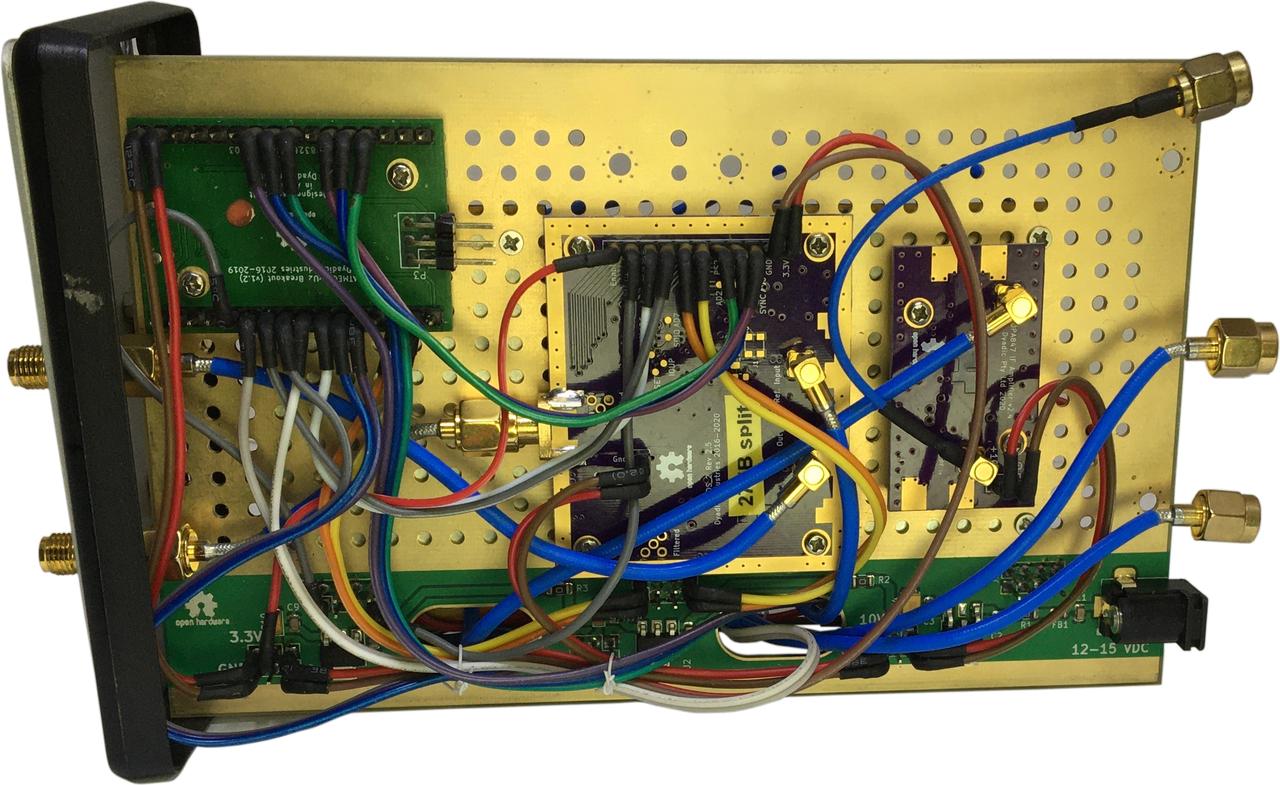
Figure 7a: Top side of assembly.
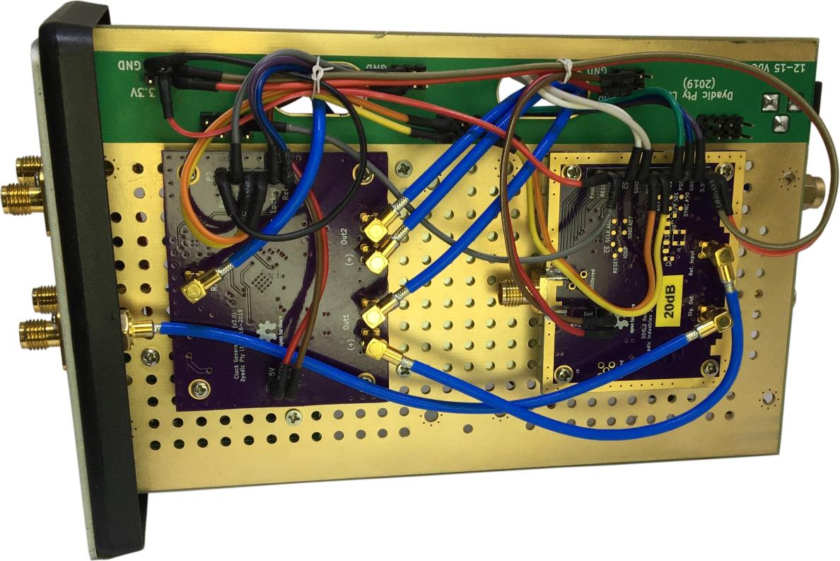
Figure 7b: Reverse side of assembly.
The DDS Signal Generator App Source Code
A full description and code for the DDS signal generator app is given here: ddsgen.py.