
RF Blocks - Open RF Prototyping
RF Blocks provides a ready made hardware and software platform together with a set of hardware modules which can be quickly and easily integrated into functional RF systems for experimental or prototyping purposes.
Features
Hardware Modules and software. All the hardware design files are licensed under CERN-OHL-S v2 and include full schematics and board layouts.
Characterised designs with documented typical characteristics, design notes and reference designs.
Reusable hardware modules with options to allow their use in many different designs.
Compact integration of hardware modules into standard aluminium enclosures using standard interconnects
Support for Red Pitaya boards
Hardware modules can be individually shielded
-
Applications include:
Test equipment
Signal conditioning
Signal generation and synthesizers
Up/down converters
ADC/DAC front ends
Receivers
Modulators
Hardware Modules
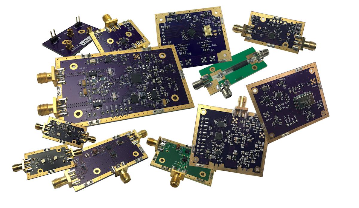
An index of currently available hardware module designs is available here: RF Blocks Hardware Modules
Reference Designs
An index of reference designs making use of RF Blocks hardware and software is available here: RF Blocks Reference Designs.
Software Support
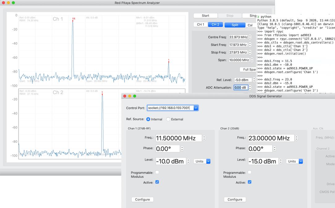
Software support is provided by embedded control software, Python packages and example applications for hardware reference designs. Details are available here: RF Blocks Software and Firmware
Redpitaya Support
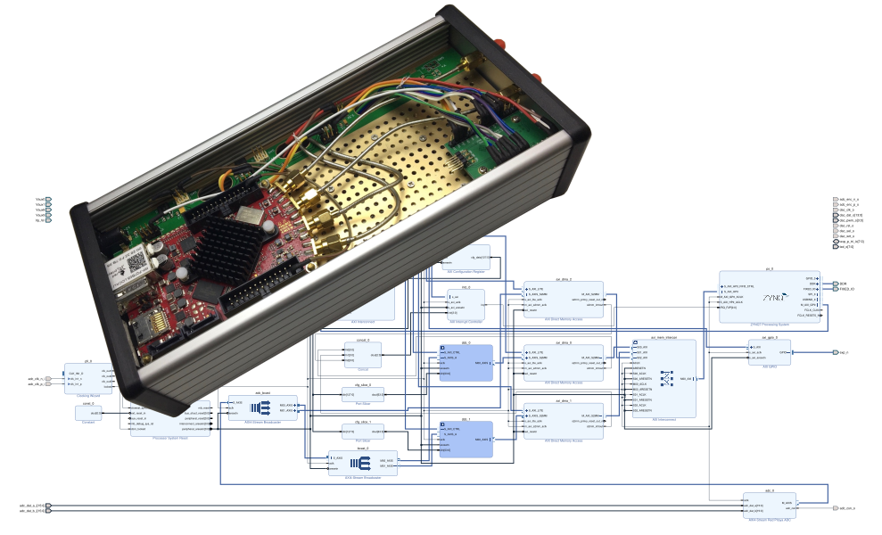
RF Blocks module carrier boards includes provision for mounting a Red Pitaya board. This allows the close integration of the Red Pitaya with RF Blocks modules. RF Blocks provides FPGA designs and associated software to use the Red Pitaya for signal acquisition and generation. Details are available here: RF Blocks and Red Pitaya.
Prototyping System
Prototype RF systems are created by integrating functional modules onto module carrier boards which are then installed inside one or more enclosures. For our purposes the modules, carrier board and enclosure is referred to as a module assembly. Figure 2a illustrates an example of a module assembly.
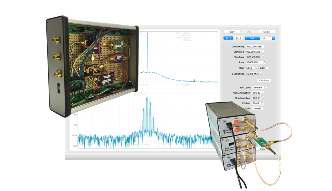
In most cases each module assembly will include either a USB/RS-232 microcontroller or take SPI and GPIO control lines from an external source via the SPI control connector mounted at the rear of the enclosure. Multiple module assemblies can therefore be used together to implement larger prototype systems. Figure 2b illustrates the use of multiple module assemblies in the measurement of mixer IMD.
Further details of the various components in the prototyping system are described in the sections below.
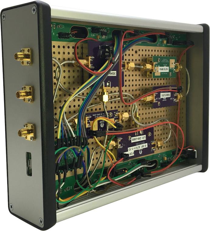
Figure 2a: An example of modules assembled into a functional design.
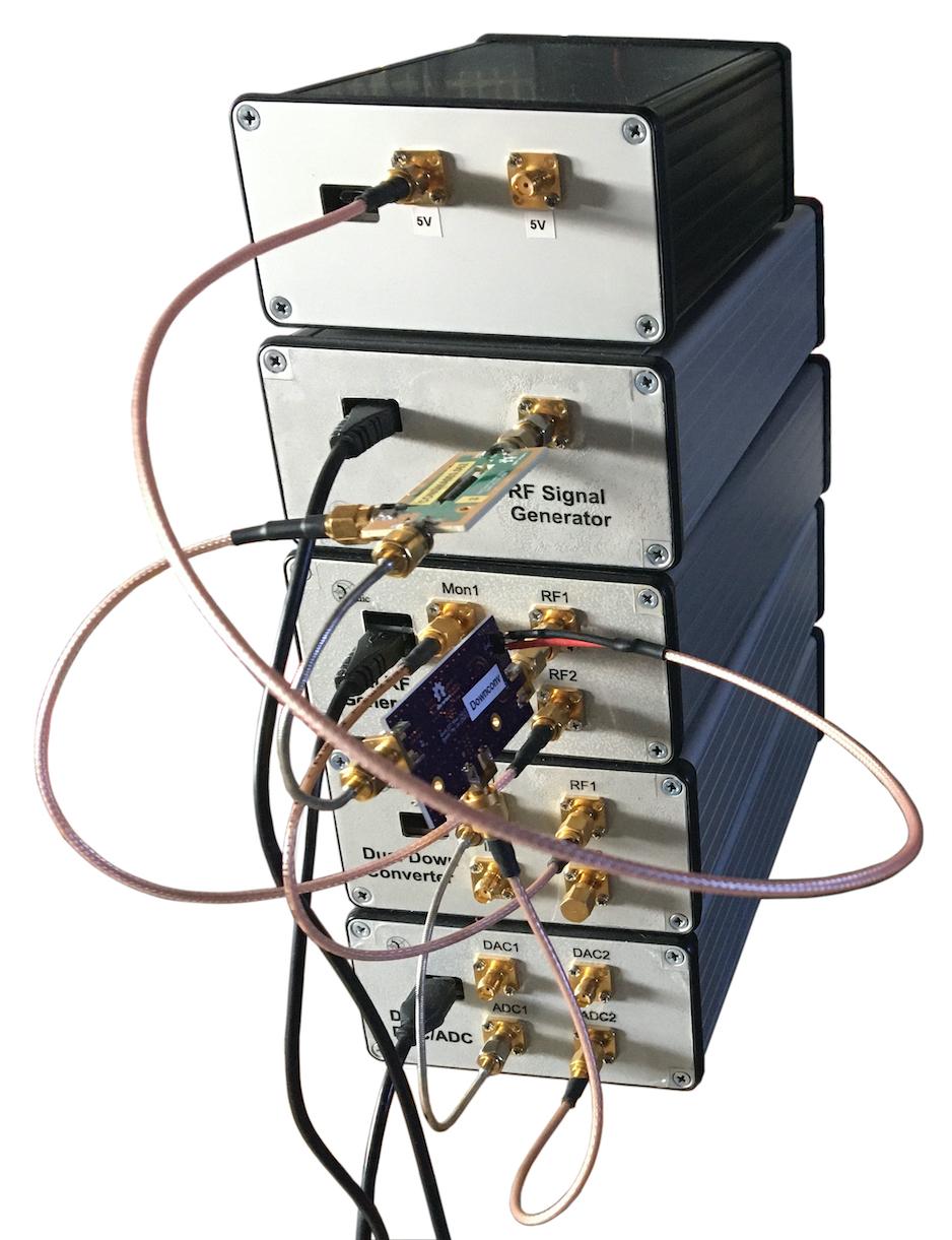
Figure 2b: Module assemblies being used to test mixer IMD.
Module Carrier Boards
The module carrier boards are standard eurocard sizes and are designed to fit enclosures such as the Hammond 1455 series extruded aluminium cases. Currently available board sizes: 100mm x 160mm (N160), 100 x 220 (N220), 160mmx220mm (T220) which will fit Hammond enclosures 1455N1601, 1455N2201, and 1455T2201 respectively.
The carrier boards accept input power via a standard barrel connection and provide on board voltage regulation: 10V, 5V and 3.3V are the standard available supplies. KiCad design files for the boards are available here: 1455N160, 1455N220, 1455T220.
The carrier boards are designed to allow hardware modules to be mounted on both sides. Pass through connectors and slots are provided to allow passage of both RF coax. connections and control and power between sides.
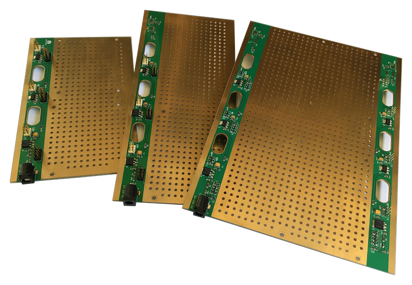
Figure 3a: N160, N220, and T220 module carrier boards.
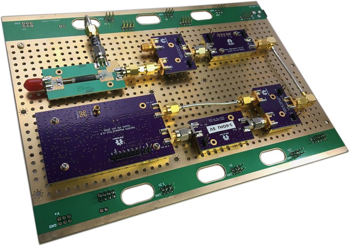
Figure 3b: T220 module carrier board with some attached modules.
RF coax. connections
RF connections are constructed from hand formable cable and either SMA or MMCX connectors. Depending on the frequency of operation, the cable may be either 0.086 or 0.047 inch. The thinner 0.047 inch cable is more easily routed but return loss may be an issue above approximately 2 GHz.
For cable connections with multiple bends the bend radius should be kept to 25 mm. For single bends, a 10 mm radius should be the minimum.
There are a number of sources for coaxial cable assemblies of varying quality and price.
Crystek offer hand formable 0.086 in SMA male to male cable assemblies of various lengths: 0.086 50 ohm Hand Formable Coaxial Cables. These are reasonably priced and have good performance characteristics to 12 GHz.
Minicircuits also offer hand formable 0.086 in cable assemblies with a choice of connectors and lengths: RF Cables. These have good performance and are priced competitively.
Custom built cables are also available from at least one China based supplier: Custom Cable Assemblies. These are definitely in the 'budget' category but are certainly adequate as long as the performance constraints are understood.
In some circumstances ready made cable assemblies may not be available with the required connectors. In these cases custom cable assemblies can be used. Again, the performance limitations of the Chinese products must be understood in order to ensure that the quality of the design is not compromised.
Finally, cable assemblies can be constructed by 'hand'. This is not difficult to do but can be time consuming.
A performance comparison of RF cable assemblies from various sources: RF Cabling Performance.
Power and control
Power and control connections are terminated on standard 0.1" pitch male pin headers.
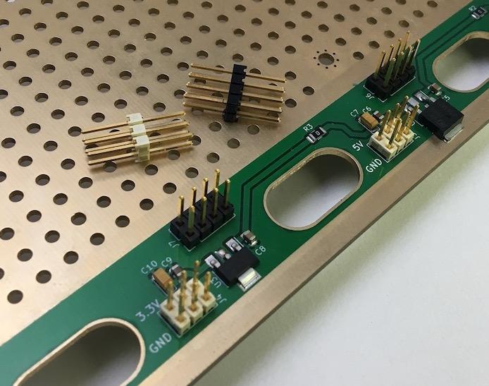
Figure 4a: Carrier board power and control connectors.
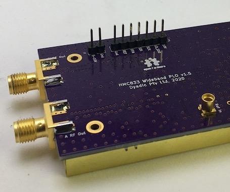
Figure 4b: Example of control and power pins on a module board.
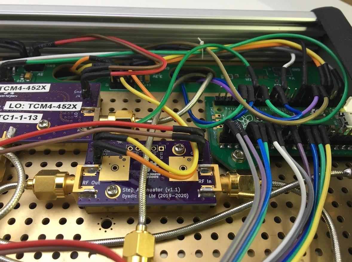
Figure 4c: An example of carrier board power and control connections.
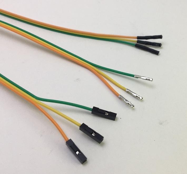
Figure 5: Control and power wires
Power and control lines are the usual multistrand hookup wire terminated with dupont style connectors. The plastic insulation pieces at the ends of the wires are replaced with heat shrink tubing as shown in Figure 5.
Remove the plastic insulation pieces.
Add heat shrink tubing to the Dupont terminations.
Note that the Dupont terminations can be bent to become right angled. This allows the height requirements for integrated modules on module carrier boards to be reduced. This in turn allows module carrier boards to be populated on both sides and still fit into the Hammond 1455 style enclosures.
Shielding
Shielding for the hardware modules is a nickel coated steel shim 'tin' held in place on the module by Harwin shield clips. It's also fairly straightforward to fabricate shielding from brass shim. Holes in the shield allow the attachment of brass standoffs to the carrier board.
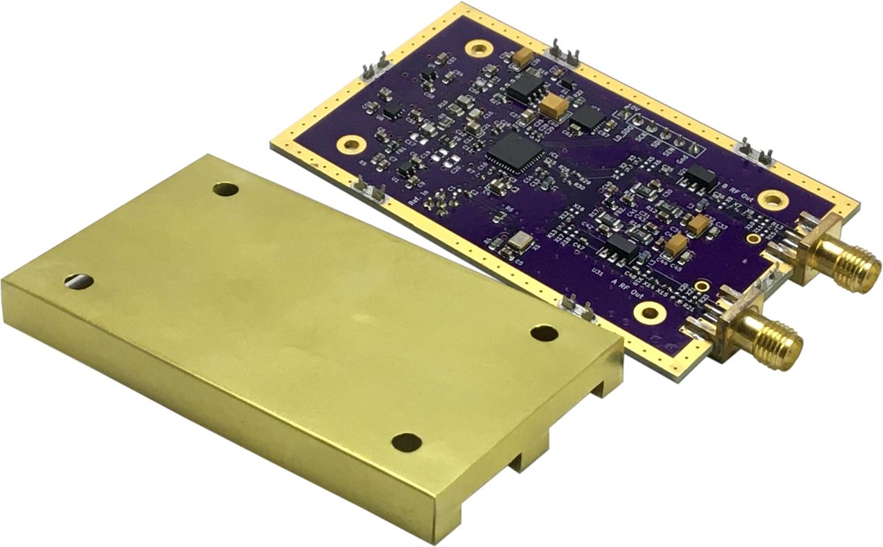
Figure 6a: Module shielding.
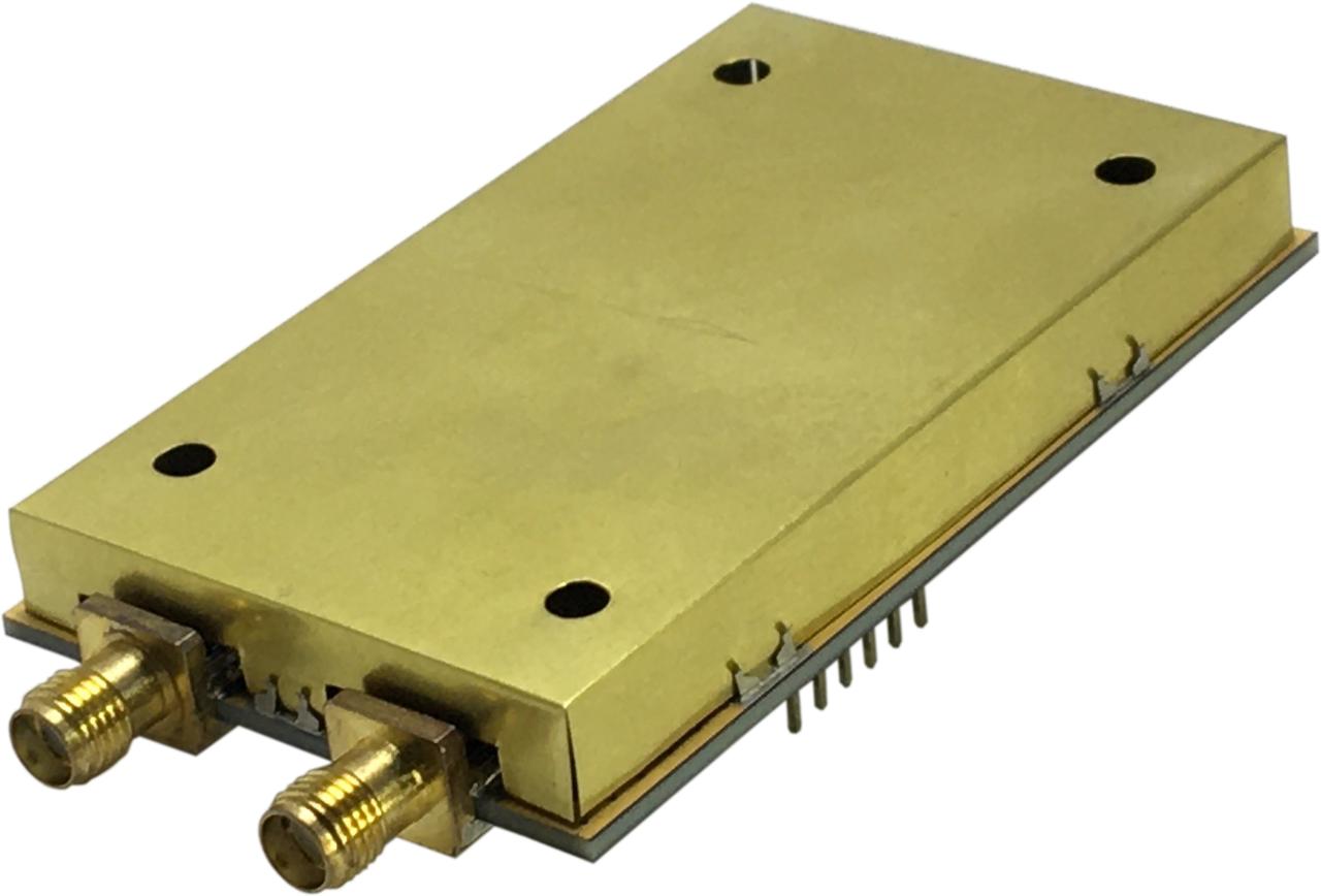
Figure 6b: Module with shielding attached.
Shields may be mounted on both sides of the carrier board. The use of countersunk screws also allows modules to be mounted 'overlapping' style. There is sufficient clearance between board standoffs and shield holes so that standoffs can be attached to the carrier board and the associated modules fitted afterwards.
Enclosure
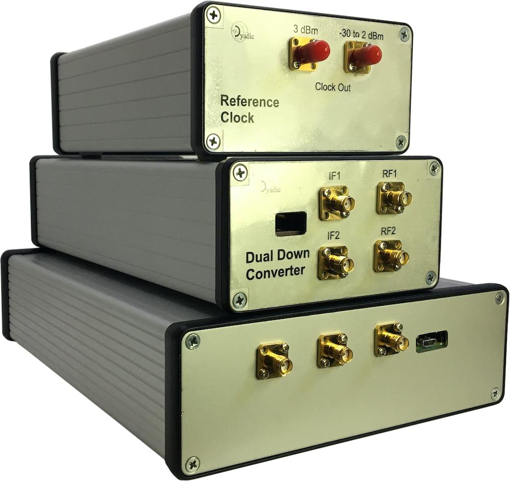
Figure 7a: Module assembly enclosures using Hammond series 1455
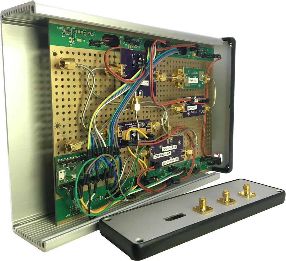
Figure 7b: Example use of Hammond 1455T220 enclosure (without the top)
The Hammond 1455 extruded aluminium cases.
Enclosures for smaller functional units such as filters, amplifiers, attenuators.
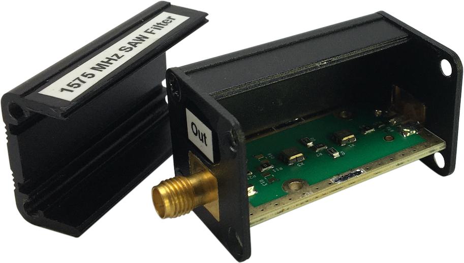
Small enclosure for a SAW filter
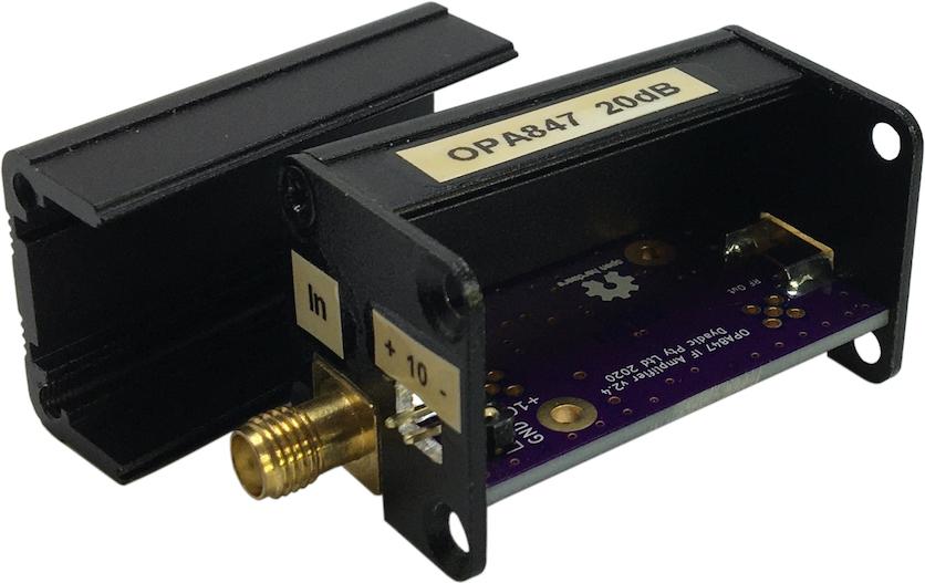
Small enclosure for an amplifier
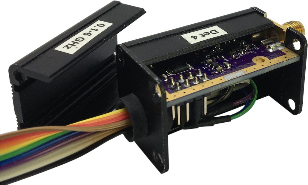
Small enclosure for power sensor