
Direct Conversion RF Front End
Hardware Setup
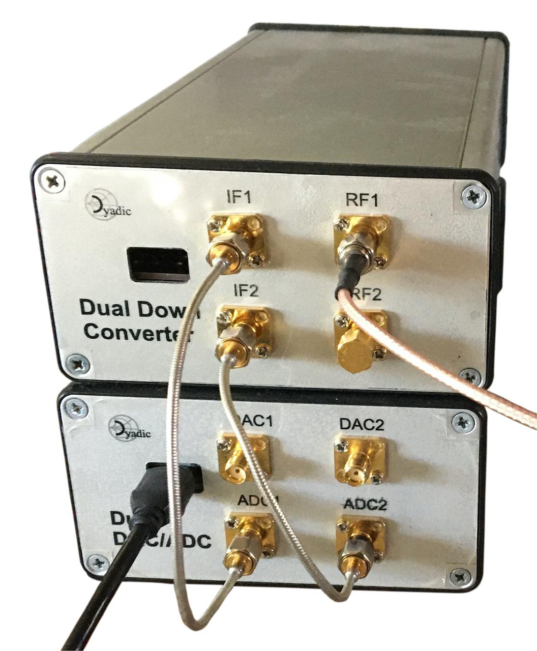
Figure 1a: Front connections.
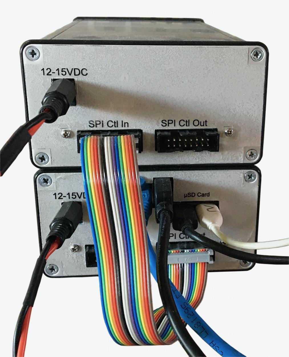
Figure 1b: Rear connections.
The direct conversion front end makes use of the HMC833 synthesizer as local oscillators and therefore the power up sequence should be as follows:
Ensure that the RPSA USB control cable is connected first.
Power the RPSA on.
Connect the SPI/GPIO cable to the SPI Input of the direct conversion front end.
Now power the direct conversion front end on.
More information about the HMC833 power up sequence is provided here: HMC833 Applications Information.
The FrontEnd App
usage: frontend [-h] -d DEVICE [-b BAUDRATE] [-A IPADDR] [-P PORT] [-F FRONTEND_CONFIG]

Red Pitaya RF Front End

optional arguments:
  -h, --help            show this help message and exit
  -d DEVICE, --device DEVICE
                        The front end hardware serial device
  -b BAUDRATE, --baudrate BAUDRATE
                        Baud rate (default: 0)
  -A IPADDR, --ipaddr IPADDR
                        IP address for the RPyC server instance
  -P PORT, --port PORT  TCP port for the RPyC server instance
  -F FRONTEND_CONFIG, --frontend_config FRONTEND_CONFIG
                        Frontend hardware configuration.
Configuration and capabilities
Typical Characteristics

Figure 2: Direct down converter phase noise.

Figure 4: Direct down converter IIP3 for various values of front end attenuation.

Figure 3: Direct down converter IMD as a function of front end attenuation.

Figure 4: Direct down converter channel cross talk.
Assembly
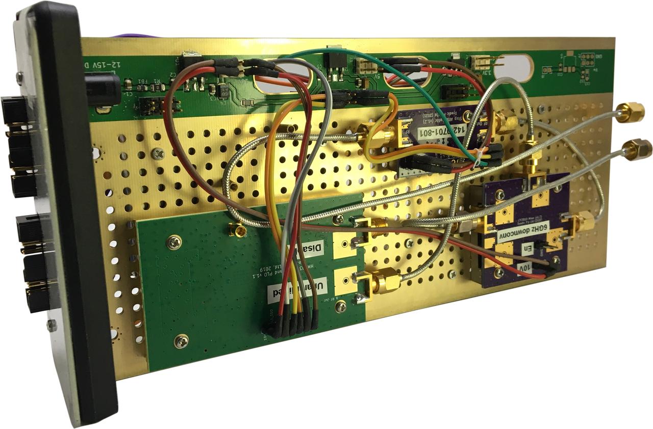
Figure 5a: Top side of assembly.
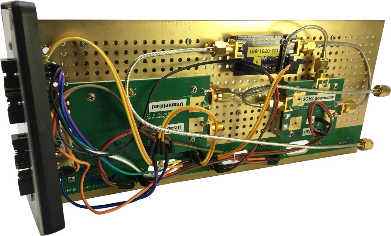
Figure 5b Reverse side of assembly.
Design Notes

Figure 6a: Direct down converter IM3 test setup.
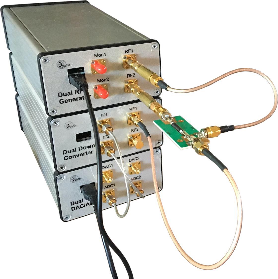
Figure 6b: Direct down converter IM3 test hardware setup.

Figure 7: Direct down converter module schematic.
Application Source Code
A detailed description of the direct conversion front end application app code is provided here: Direct Conversion Front End