Phase Noise Measurement with the HP11729C
A Phase Noise Measurement App Using the HP11729C
This document describes the use of an aplication to automate the measurement of phase noise using the HP11729C. The document is in three parts:
Some preliminaries describing the type of phase noise measurement.
The instrument set up required to undertake the measurements.
Using the application to perform the measurements.
Preliminaries
Phase noise measurement is a fairly crucial requirement when designing and building signal generating devices. Recent spectrum analyzer models from Rohde & Schwarz, Agilent and others offer good phase noise measurement facilities but the cost of these will generally be beyond the means of most individuals or small businesses. In general, budget spectrum analyzers do not have the required phase noise characteristics to make reliable measurements of phase noise particularly for close in carrier offsets. However, the HP11729C offers an alternative for making accurate, close in phase noise measurements. The HP11729C Carrier Noise Test Set allows phase noise measurement using either the phase detector or the frequency discriminator methods. These units can now be picked up on Ebay for reasonable prices.
In our work we are interested in phase noise measurements of phase locked oscillators and synthesizers. In particular, we are interested in phase noise characteristics down to approximately 1 kHz carrier offsets or less. The frequency discriminator phase noise measurement method is not suited for this application due to it's decreased sensitivity at low to moderate carrier offsets. We therefore confine our attention to the phase detector measurement method.
In outline, the phase detector method works as follows. Signals from the device under test (DUT) and a reference source are mixed. The system behaves as a phase detector if the input signals to the mixer are adjusted to be in phase quadrature. When they are in quadrature the nominal DC output voltage from the mixer is 0 Volts. The output from the mixer is then a direct measure of the phase difference between the two signals, and is therefore also a direct measure of the phase noise of the DUT (provided the reference signal is of higher quality than the DUT). This meathod of phase noise measurement requires a good quality reference signal source - the phase noise noise of the reference signal should, ideally, be 10 to 15 dB below that of the signal being measured. The HP product note 11729B-1 ("Phase Noise Characterization of Microwave Oscillators - Phase Detector Method") provides a detailed description of the phase detector method and the use of the HP11729 instruments.
Measurement Setup
The phase noise measurement setup we use consists of the following pieces of equipment:
- An HP11729C Carrier Noise Test Set
-
This was acquired off Ebay for a very reasonable sum. The unit came equipped with option 003, two installed bands 10 MHz to 1.28 GHz and 1.28 GHz to 3.2 GHz.
- A Rohde & Schwarz SMHU signal generator
-
The SMHU has very good phase noise characteristics as well as providing an external FM modulation facility which can be connected to the HP11729C
FREQ-CONT DC-FMoutput.Figures 1a and 1b show the SMHU phase noise characteristics as given by the SMHU data sheet.
Figure 1a: SMHU phase noise characteristics.
Figure 1b: SMHU typical phase noise at 1 GHz.
Note that the noise floor is a little high at -150 dBc and compromises the measurement of the noise floor for some of the better synthesizer components now available.
- An HP8560A spectrum analyzer
-
This provides coverage down to 50 Hz (with DC coupled input) and can be used to directly display the noise spectrum from the HP11729C.
Figure 2 shows the connections between the various pieces of equipment
in order to implement the phase detector method. For a test signal
in the range 5 to 1280 MHz the 640 MHz connection is not required.
For test signals greater than 1280 MHz a 640 MHz signal (\(\pm 32\) kHz)
must be connected to the 640 MHz IN connection on the rear of the HP 11729C.
The level of this signal must be between 1 and 4 dBm. Note that the
640 MHz signal should be high quality. In the HP 11729C Operation manual
it is recommended that the 640 MHz output from the HP 8662A signal generator
be used.
Offset from Carrier |
dBc/Hz |
|---|---|
1 kHz |
-96 |
10 kHz |
-126 |
100 kHz |
-145 |
1 MHz |
-155 |
10 MHz |
-157 |
Failing this, the 640 MHz signal from HP 11729C itself can be used by
connecting the 640 MHz OUT and 640 MHz IN on the rear of the
unit with the supplied HP cable attenuator. Doing this may degrade the
noise floor of the system close in to the carrier. Whether this is a problem
or not will depend on the quality of the signal source being measured.
If it is thought that the test source has phase noise comparable to or
less than -110 to -115 dBc at offsets of approximately 10 kHz (for a test
frequency > 1280 MHz) then a better 640 MHz source is required.
Table 1 lists the absolute phase noise of the internal 640 MHz SAW oscillator as
given by the HP 11729C Operation manual (Table 1-2).
The FREQ-CONT DC-FM output on the rear of the HP 11729C is connected to
the FM/ \(\Phi\) M EXT input on the front of the SMHU. When DC coupling
is activated on this input by selecting FM__EXT DC the SMHU will operate
as a VCO with the externally applied voltage from the HP 11729C FREQ-CONT DC-FM
output (in the range -1 to +1V) tuning the SMHU. The tuning range will be
determined by the FM modulation deviation setting in effect on the SMHU.
The deviation is set by entering FM__<dev>__<unit>.
For example, a deviation of 2 kHz is set by FM__2__kHz.
Refer to the Rohde&Schwarz SMHU Operating manual
Sections 2.3.29 (Modulation, External Source) and 2.3.16 (Modulation, FM)
for further details if required.
Figure 2: Phase noise measurement: phase detector configuration.
The reference signal from the SMHU to the 5 TO 1280 MHZ input on the
HP 11729C should be 0 dBm \(\pm\) 1 dBm. The frequency of the reference
signal should be determined by looking at the IF OUTPUT from the
HP 11729C. The signal with the highest amplitude will be the actual
IF signal and the reference should be set to this. If the test signal
is < 1280 MHz the IF signal will also be this value. However, if the
IF signal is close to 640 MHz the position of any high level spurs
should be noted. These can occur for IF signal between 625 and 655 MHz
and care must be taken to avoid using these during the calibration
procedure.
From the HP-11729C Operation manual, the MICROWAVE TEST SIGNAL
input should have the following level:
For test frequencies <1.28 GHz: -5 dBm to +10 dBm. Typically usable down to -15dBm with potential noise floor degradation; optimal level from -2 dBm to +3 dBm.
For test signals >1.28 GHz: +7 dBm to +20 dBm. Typically useable down to -15 dBm with potential noise floor degradation.
Finally, connect the NOISE SPECTRUM, < 10 MHz output to the input of the
spectrum analyzer. In the case of the HP 8560A this must be done via
a low frequency DC block since the spectrum analyzer will be used
with it's input DC coupled. We use a DC block consisting of two 47 uF
surface mount tantalum capacitors in parallel. Together with the (nominally)
50 \(\Omega\) input impedance of the analyzer, this provides a high pass
response of 3 dB at approximately 30 Hz. This should be sufficient
given the 50 Hz low frequency response of the HP 8560A when DC coupled.
Making Phase Noise Measurements
Initialization
The application makes use of an Ethernet to GPIB controller. On startup,
the default address for this controller is displayed in the GPIB Controller combo box control. This should be modified to match the
actual IP address if necessary. Selecting Initialize will then
initialize communications with test instruments.
Any errors encountered during the instrument initialization will be displayed as popup windows. For example, an error will be dislayed if any of the instruments are powered down or offline.
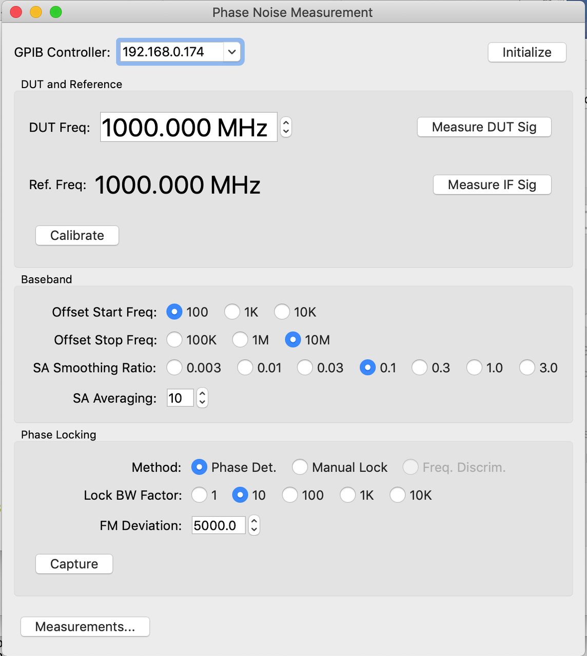
Figure 3: Application initialization
Set DUT and Ref. frequencies
The DUT frequency is entered into the DUT Freq text field. The Measure DUT Sig can optionally be selected in order to make an automated
measurement of the DUT frequency. If this is done a prompt popup will
request that the DUT signal is connected to the spectrum analyzer input
before proceeding.
The frequency of the phase noise reference will be automatically
calculated based on the specified DUT frequency and shown in the
Ref. Freq. field. If a check of the IF signal is desired then
Measure IF Sig should be selected. A prompt dialog will then request
that the IF output from the HP11729C be connected to the spectrum
analyzer input before proceeding.
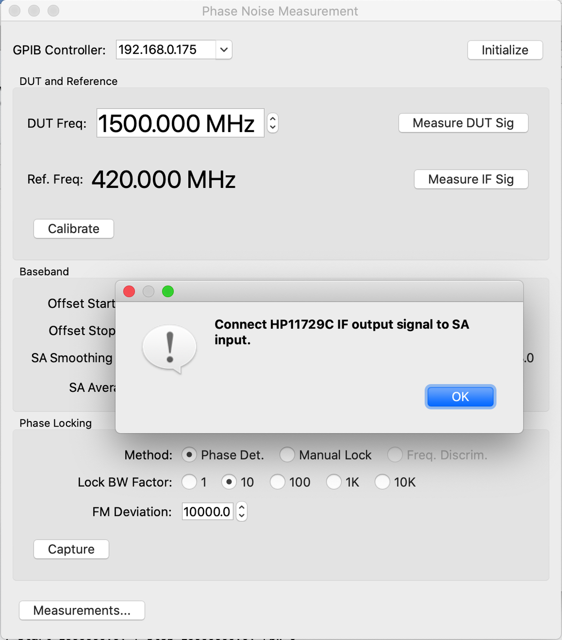
Figure 4: Measure IF signal
Calibration
Before continuing with calibration make sure that the HP11729C IF output is disconnected from the spectrum analyzer and terminated.
The test setup must now be calibrated. This is done by selecting the
Calibrate button. This will prompt for HP11729C < 10MHz output be
connected to the spectrum analyzer. Note that a DC block **must** be
used on the spectrum analyzer input. Selecting OK will initiate the
calibration process. After calibration completes several internal
parameters will be set to optimal values and the Capture button will be
enabled.
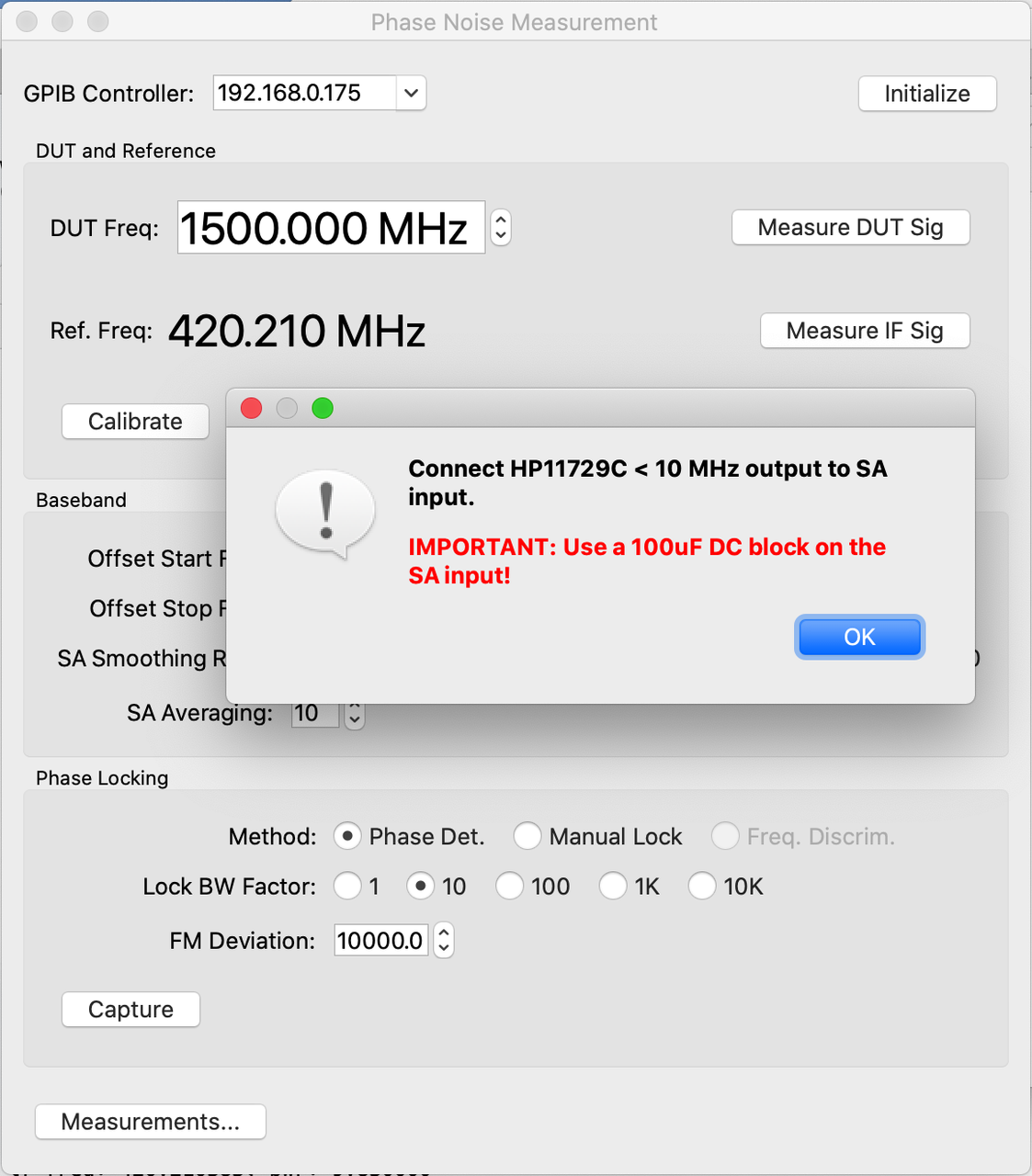
Figure 5: Initiate calibration
Attaining phase lock
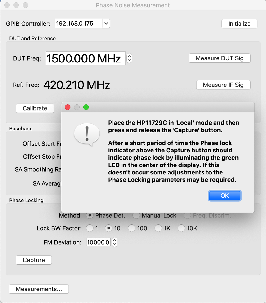
Figure 6: Initiate phase lock
Phase noise sweep
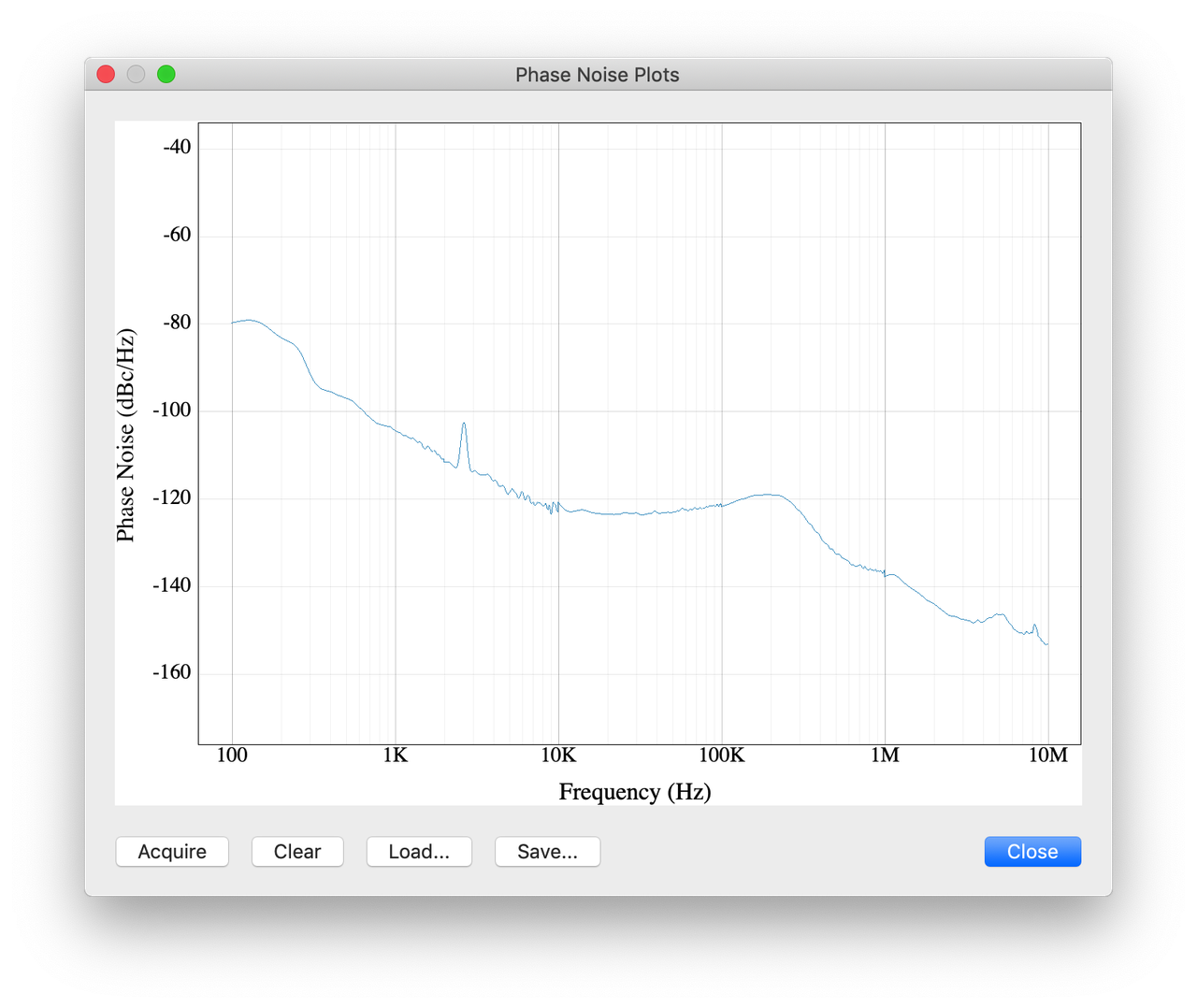
Figure 7: Phase noise sweep
Save phase noise data
Application Source Code
Documented source code for the application is available here: Phase noise measurement application.