An LTC5510 Based Active Mixer
Features
\(50\Omega\) matched input for 30 to 3000 MHz.
High linearity: OIP3 of 27 dBm at 1500 MHz, input P1dB 11 dBm.
Up- or down-conversion.
Input/LO range to 6000 MHz.
0 dBm LO drive level.
Excellent LO to RF isolation: 65 dB at 1100 MHz. LO to IF isolation 41 dB.
Noise figure 11.6 dBm at 1500 MHz.
Typical Performance Characteristics
Return loss
Gain and IP3
Mixer module populated with MABA-011082 input balun, BD1222 output balun.
Mixer module populated with MABA-011082 input balun, MABA-010129 output balun.
Isolation
Application Information
Board connector configuration
Board Pin |
Type |
Description |
|---|---|---|
|
Input |
Mixer enable |
|
Signal Input |
Mixer RF input |
|
Signal Input |
Mixer LO input |
|
Signal Output |
Mixer differential IF output |
|
Power Input |
6-12V DC power input |
|
Power Input |
Module ground |
Figure 1a: Active mixer module connector layout (SMA connectors)
Figure 1b: Active mixer module connector layout (MMCX connectors)
Reference Designs
Design Notes
Schematic
Layout
Low frequency up conversion
The input needs to be matched in the frequency range < 1 GHz. For the range 30 MHz to around 2.5 GHz leaving C1 unpopulated provides a good match. For frequencies < 30 MHz, C1 should probably be populated with a 1 to 2 nH inductor. According to the Qucs model for the RF input port this match should extend up to 2.5 GHz.
The output should be matched for the approximately 1 GHz IF frequency. On the IF output L2 and L3 are left unpopulated. L4 and L5 are are 15 nH 0603HP inductors. According to Table 6 of the LTC5510 datasheet this configuration should provide a reasonable IF output match across the frequency range 10 to 1300 MHz. VNA measurement indicates:
Return loss of < 10 dB for < 1100 MHz.
< 25 dB for < 40 MHz
< 15 dB for 800 to 1060 MHz
Wideband up conversion
Down conversion
Tests
Conversion loss
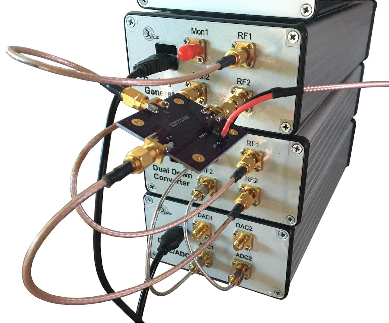
Figure 10a: Mixer conversion loss test setup.

Figure 10b: Mixer conversion loss hardware test setup