
MMIC Amplifier Block
Features
Board design for general MMIC amplifiers.
SMA or MMCX connectors.
Customizable input/output networks.
Allow common MMIC package footprints: SOT-89, DFN-6, SOT-86.
Optional input filter.
Characterized example designs.
Typical Characteristics
Typical characteristics of the gain block boards variants are presented in the sections below. In each section characteristics for board sets using specific MMIC amplifers are presented. Table 1 summarizes the boards.
Section |
Device |
Gain |
NF |
OP1dB |
OIP3 |
Power requirements |
Board variant |
|---|---|---|---|---|---|---|---|
SKY65014 |
15 |
4.8 |
18 |
36 |
5V @ 80mA |
SOT-89 |
|
SKY65017 |
18 |
4.5 |
20 |
33 |
5V @ 80mA |
SOT-89 |
|
GRF2014 |
15 |
4.0 |
24 |
42 |
5V @ 160mA |
DFN-6 |
|
GRF2014 |
16 |
3.5 |
27 |
44 |
10V @ 175mA |
DFN-6 |
|
GRF2014 |
16 |
3.5 |
23 |
44 |
10V @ 160mA |
DFN-6 |
|
GRF2014 |
14 |
4.0 |
24 |
42 |
5V @ 160mA |
DFN-6 |
|
GRF2014 |
14 |
3.5 |
24 |
42 |
5V @ 165mA |
DFN-6 |
|
GRF2013 |
16 |
1.6 |
22 |
37 |
5V @ 80mA |
DFN-6 |
|
GRF2013 |
14 |
2.0 |
20 |
32 |
5V @ 95mA |
DFN-6 |
|
GRF2013 |
15 |
1.8 |
20 |
35 |
5V @ 85mA |
DFN-6 |
|
GRF4014 |
28 |
3.0 |
22 |
32 |
5V @ 65mA |
DFN-6 |
SKY65014 general purpose gain block

Figure 1a: Measured S-parameters for the SOT-89 board using SMA connectors ad populated with the SKY65014 MMIC. The dashed light grey curves are the device S-parameter magnitudes as supplied by Skyworks (SKY65014 S-parameters).

Figure 1b: Measured S-parameters for the SOT-89 board using MMCX connectors and populated with the SKY65014 MMIC. For comparison, the dashed line shows the measured S-parameters for the SMA board variant.
GRF2014 linear driver

Figure 3a: Measured S-parameters for the DFN-6 board using SMA connectors and populated with the GRF2014 MMIC. The dashed light grey curves are the device S-parameter magnitudes as supplied by Guerrilla RF (GRF2014 S-Parameters).

Figure 3b: Measured S-parameters for the DFN-6 board using MMCX connectors and populated with the GRF2014 MMIC. For comparison, the dashed line shows the measured S-parameters for the SMA board variant.
SKY65017 broadband gain block

Figure 2: Measured S-parameters for the SOT-89 board using SMA connectors ad populated with the SKY65017 MMIC. The dashed light grey curves are the device S-parameter magnitudes as supplied by Skyworks (SKY65017 S-parameters).
GRF2014 50-3000MHz tune

Figure 4: Measured S-parameters for the GRF2014 SMA board with 50-3000 MHz tuned matching networks.
GRF2014 500-3000MHz tune

Figure 4: Measured S-parameters for the GRF2014 SMA board with 500-3000 MHz tuned matching networks.
GRF2014 100-1800MHz tune
This variant is designed to deliver higher output powers (up to 25 dBm) with an OP1dB of approximately 27dBm.

Figure 5: Measured S-parameters for the GRF2014 SMA board with 100-1800 MHz tuned matching networks.
GRF2014 30-1000MHz tune

Figure 5: Measured S-parameters for the GRF2014 MMCX board with 30-1000 MHz tuned matching networks.
GRF2013 50-3000MHz tune

Figure 5: Measured S-parameters for the GRF2013 SMA board with 50-3000 MHz tuned matching networks.
GRF2013 3000-6000MHz tune

Figure 6: Measured S-parameters for the GRF2013 SMA board with 3000-6000 MHz tuned matching networks.
GRF2013 400-5000MHz tune

Figure 7: Measured S-parameters for the GRF2013 SMA board with 400-5000 MHz tuned matching networks.
GRF2013 with 1GHz LP filter

Figure 8: Measured S-parameters for the GRF2013 SMA board with 1 GHz LP filter.
GRF4014 10-300MHz tune

Figure 7: Measured S-parameters for the GRF4014 SMA board with 10-300 MHz tuned matching networks.
Design Notes
Board variants
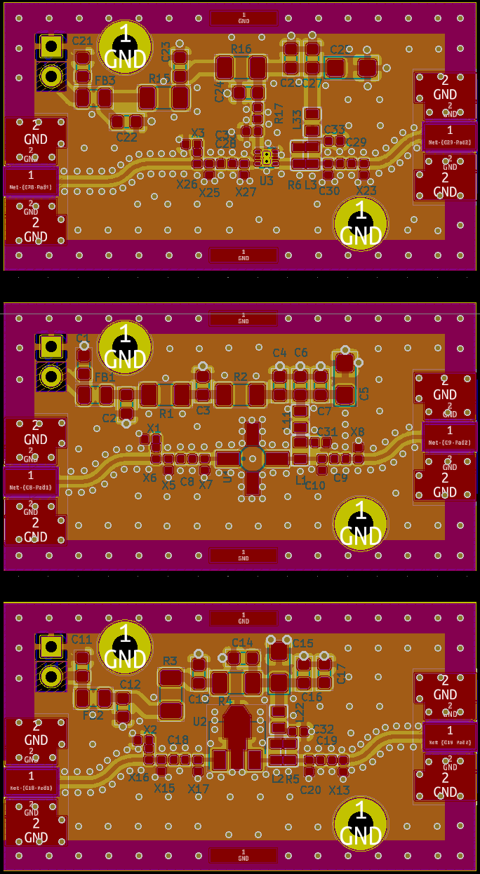
Figure 7a: Gain block board variants with SMA connectors. The top panel is the DFN-6 layout, the middle panel is the SOT-86 layout and the bottom panel is the SOT-89 layout.
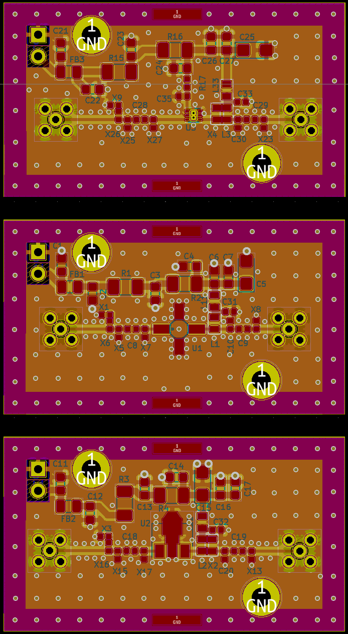
Figure 7b: Gain block board variants with MMCX connectors. The top panel is the DFN-6 layout, the middle panel is the SOT-86 layout and the bottom panel is the SOT-89 layout.
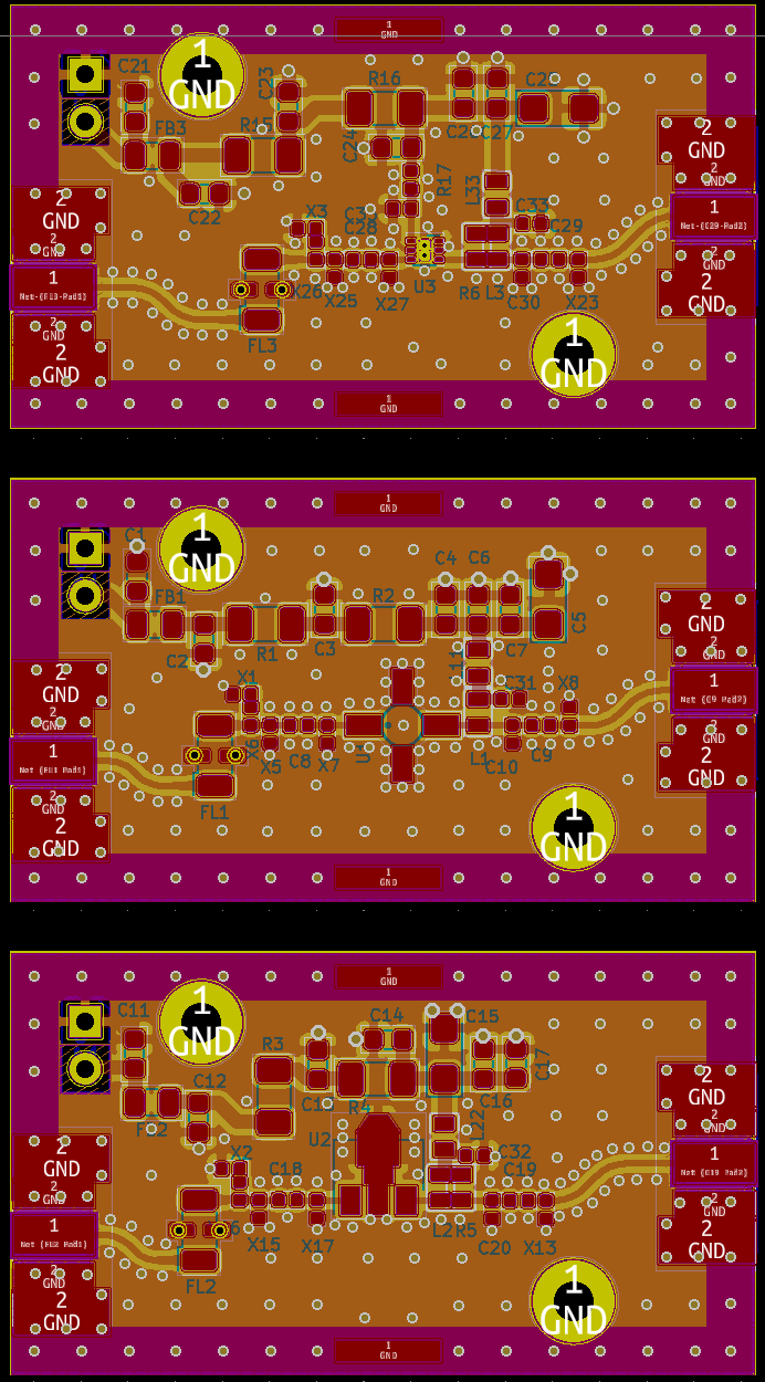
Figure 7b: Gain block board variants with input filtering. The top panel is the DFN-6 layout, the middle panel is the SOT-86 layout and the bottom panel is the SOT-89 layout.
SKY65014 gain block

Figure 8: Schematic for SKY65014 general purpose gain block.
SKY65017 gain block

Figure 8: Schematic for SKY65017 wideband gain block.
GRF2014 tunes
Ven is 3.1V. From the GRF2014 30-800MHz custom tune document, Ien = 5.6mA
gives Iddq = 152mA. Set Vdd to be 8V. With R17 set to \(910\Omega\), Ien
= 5.4mA which results in an Iddq of approximately 165mA. With a board
input voltage of 10V and setting R15 and R16 to \(5.6\Omega\) results in
Vdd of 8V with a total supply current of 170mA.

Figure 8: Schematic for GRF2014 design using 50-1000 MHz tuning.

Figure 8: Schematic for GRF2014 design using 100-1800 MHz tuning.

Figure 8: Schematic for GRF2014 design using 500-3000 MHz tuning.

Figure 8: Schematic for GRF2014 design using 50-3000 MHz tuning.
GRF2013 tunes

Figure 8: Schematic for GRF2013 design using 50-3000 MHz tuning.

Figure 8: Schematic for GRF2013 design using 400-5000 MHz tuning.

Figure 9: Schematic for GRF2013 based design using 3000-6000 MHz input/output matching.
GRF4014 tunes

Figure 9: Schematic for GRF4014 based design using 10-300 MHz input/output matching.
Gain block/filter combinations

Figure 9: Schematic for GRF2013 based design using 50-3000 MHz input/output matching.